This paper introduces the general and basic functions of the general software "Microwave Office" (Microwave Office) and its two simulators for the calculation of microwave planar circuits introduced by AWR in the United States in recent years. From the user's point of view, the advantages and disadvantages of the software are analyzed. Two examples of calculations are given.
1 IntroductionSince the 1980s, international microwave circuit technology has shifted from traditional waveguide and coaxial components and systems to microwave planar circuits (also known as microwave integrated circuits or microwave printed circuits), which are characterized by the printing of circuits. On the plane of the dielectric substrate. Volume, weight and cost are greatly reduced. In addition to microstrips, coplanar waveguides, slot lines, suspension lines and other passive circuits, microwave semiconductor devices can also be integrated on planar circuits to form hybrid microwave integrated circuits. In addition to some high power and high polarization purity applications, microwave planar circuits have almost replaced various conventional forms of microwave circuits in communications, electronic warfare, radar and weapon systems.
However, designing microwave planar circuits has always been a difficult task. In recent years, design work has become more complicated: the requirements for circuit indicators are getting higher and higher, the functions of circuits are increasing, the size requirements of circuits are getting smaller and smaller, and the design cycle is getting shorter and shorter. To cope with this challenge, Applied Wave Research of California, USA, spent ten years researching a software called Microwave Office, which is said to provide the most complete and most complete microwave plane design. Fast and most accurate solution. This software works under the Windows 95/98/NT operating system and uses object-oriented program technology, which is easy to use. A microwave engineer with an average level of computer operation and college English can usually master the most basic use of the software by learning the help files provided by the software within three to four weeks. However, it is not easy to fully grasp the use of the software, it takes 3-6 months or more. The company claims that the software is inexpensive and its purpose is to enable microwave companies to install it on every engineer's computer desktop like a tool. As far as I know, the $30,000 price that the company asks is not easy for most domestic users, but because it allows copying and sharing on the network, there are many computers, and large companies with internal networking are still acceptable. For promotion, AWR offers a trial version of the "Microwave Office (version 2.5)" software on its Internet site. By downloading and requesting a password, you can get a free trial of one month. You can also apply for a trial or purchase from the company's agent in China, Staples.
The software is currently well-known internationally. For example, the famous British high-frequency research group at Queen's University, when introducing its high-frequency electronic CAD equipment on its Internet page, put "Microwave Office" and "HP" Software such as -ADS", "HP-MDS", "HP-HFSS", "Sonnet", "Mathcad", "Matlab" are listed as the most useful CAD calculation software.
2. Software features and two simulatorsIt is well known that microwave engineering problems can usually be studied by circuit methods or field methods. The "Microwave Office" software simulates and simulates microwave plane circuits through two simulators. For a circuit composed of lumped elements, it is relatively simple to use a circuit method. The software features a simulator called "Voltaire XL" to handle the microwave plane circuit problem of lumped components. For the distributed parameter microwave planar circuit composed of specific microstrip geometry, the field method is more effective. The software uses a simulator called "EMSight" to deal with the problem of three-dimensional electromagnetic fields of any multi-layer planar structure.
The Voltaire XL simulator is essentially a powerful harmonic balance and Volterra simulation engine that uses single- and multi-frequency harmonically balanced Volterra series for nonlinear circuit simulation, mixer analysis, and high-speed linear circuit analysis. , high speed noise analysis. It handles difficult microwave circuit problems with speed and accuracy superior to other models of simulators. In fact, the Volterra series analysis method is 10 to 100 times faster than the ordinary multi-frequency harmonic balance method, which is the fastest way to analyze the intermodulation of near-linear circuits. It is said to be the most exciting circuit simulator that has emerged in the last decade. The simulator has a component library. When building the circuit model, it is convenient to call up all the components used in the microwave circuit. The passive components include inductors, resistors, capacitors, resonant circuits, microstrip lines, strip lines, and the same. Axis and the like, nonlinear devices have bipolar transistors, field effect transistors, diodes, and the like. In particular, the component library collects microwave active devices and parameters from more than 30 well-known companies in the world, which is very useful for circuit design and calculation.
It is worth mentioning that the "VoltaireXL" simulator has real-time tuning capabilities. In design calculations, it is often necessary to adjust the parameters of certain components of the circuit for optimum performance. This simulator differs from other software in that it adjusts the parameters of the circuit components and does not need to recalculate from the beginning. Instead, it opens a window called “Variable Tunerâ€, selects the name of the component to be tuned, and the range of parameter tuning. . By moving the slider on the window, you can change the parameter value from minimum to maximum. The simulator's chart window immediately shows the effect of parameter changes on the overall circuit performance. This advantage is due to the fact that the simulator uses an advanced analysis technique called “incremental calculation†that avoids many repetitive calculations of the software.
The "EMSight" simulator is a complete 3D electromagnetic field simulation package that can be used for the analysis of planar high frequency circuits and antenna structures. The method is characterized by a powerfully modified spectral domain method of moments combined with intuitive window graphical user interface (GUI) technology. The simulator accurately determines the equivalent multiport network scattering parameters of the planar structure. In addition to the usual point-by-point calculations, the "EMSight" simulator also installs the Fast Sweep (FFS) algorithm. Therefore, the accuracy of the three-dimensional electromagnetic field calculated by this simulator is the same as that commonly used in the industry, but the calculation speed is much faster. It analyzes the electrical characteristics of the following circuits: Radio Frequency Integrated Circuit (RFIC), Microwave Monolithic Integrated Circuit (MMIC), Microstrip Patch Antenna, and High Speed ​​Printed Circuit (PCB).
The circuits analyzed by the "EMSight" simulator are housed in a rectangular metal box with no restrictions on the number of layers and the number of ports in the circuit. During the analysis, the simulator automatically divides the calculated object. In the place where the current density changes greatly, the mesh is finely divided, that is, the cell size is small. Where the current density changes little, the cell size is large. Users can also adjust the mesh density as needed.
The "EMSight" simulator also has the ability to display current and space electric field lines on the metal in the microwave plane circuit. The current or electric field can be displayed in three-dimensional or two-dimensional form. The arrow indicates the direction of the current or the direction of the electric field, and the depth of the color of the line indicates the strength of the current or electric field.
The "EMSight" simulator can perform many types of calculations on microwave planar circuits (called calculations in the software). In addition to calculating the impedance parameters of the circuit, admittance parameters, scattering parameters, transmission parameters, and mixing parameters, for linear circuits, it can calculate auxiliary stability factors, input capacitance, group delay, even/odd mode transmission constants/impedances/guides. Nano, voltage standing wave ratio, port input impedance / admittance, gain, etc.
The "EMSight" simulator has the ability to calculate the electric field pattern and power pattern of various line/circularly polarized microstrip antennas. The rectangular metal box boundary can be changed when calculating the antenna. The top and bottom can be changed to free space impedance. And the side walls can be pulled far. The pattern can be displayed in Cartesian or Polar coordinates, displayed in linear or logarithmic.
There is also a component library in the "EMSight" simulator, which is characterized by a large number of microstrip components such as various elbows, open routes, stubs, couplers, ladders, T-joints, etc. It also includes information on many transmission lines.
The basic requirements for installing the "Microwave Office" software for your computer's hardware are: Main frequency 200+MHz Pentium II CPU (or equivalent microprocessor system), 128 MB RAM memory, Windows 95, Windows 98 or Windows NT operation system. Workstations with more than 256 MB of memory are recommended for complex electromagnetic structures and circuits.
3. Introduction to use:The author examined the software's main functions, the ability to solve planar circuit problems, the accuracy of calculation, and the convenience of use on HP's Kayak XA small workstation. The author calculated two typical planar circuit problems: (1) rectangular microstrip patch antenna; (2) microstrip coupler. The workstation uses a Pentium II central processor with a clock speed of 300MHz, a memory RAM of 64MB, and a hard disk capacity of 4000MB.
At the beginning of the engineering design, it is often necessary to determine the basic dimensions of the microstrip line. The software provides a convenient environment for the design of the microstrip line. The software has a “Transmission Line Calculator†for five commonly used transmission lines, namely: microstrip lines, strip lines, coplanar waveguides, grounded coplanar waveguides and slot lines for extremely convenient analysis and synthesis. The calculator is actually a table. For example, analysis of microstrip lines. Simply fill in the microstrip line and the geometry of the substrate, the dielectric constant and loss angle of the substrate, the operating frequency, and then click on the “Analyze†button in the window to get the electrical parameters of the microstrip line. Includes impedance, effective dielectric constant, propagation constant, attenuation, and electrical length. For the synthesis of microstrip lines, just fill in the table with the operating frequency, impedance and electrical length of the designed microstrip line. (The size and dielectric constant of the substrate have been selected), click on the window. With the integrated button, the conductor width and length of the microstrip line are immediately available.
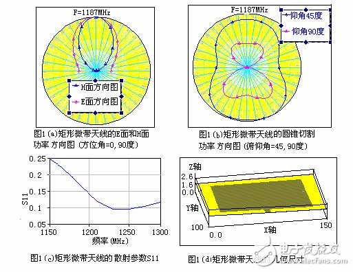
The calculation of the two instances is as follows:(1) Rectangular microstrip patch antenna
The size of the patch is a=11.43 cm, b=7.62 cm, the substrate h=1.60 mm, εr=2.62, the operating frequency F=1187MHz, and the feeding mode adopts edge feeding. The basic unit size of the XY plane where the patch is placed is selected as dx=dy=2 mm, the size of the substrate in the X direction is 150 mm, and the dimension in the Y direction is 100 mm. This is a "field" problem consisting of specific microstrip sizes. With these geometries, an EMSight electromagnetic structure can be created, as shown in Figure 1(d). The structure is divided into two layers, the upper layer is an air layer, the top plate is an open free space, and the impedance is 377 ohms; the lower layer is the dielectric substrate layer, and the bottom plate is the metal ground plane. The geometry of the microstrip antenna is established at the interface of the air and the medium. Using the EMSight simulator in the software, it is convenient to calculate the E-plane and H-plane power patterns of the antenna. The cone-cutting pattern and the scattering parameter S11 of the antenna are shown in Figure 1. The electric field patterns of the E and H planes of this example, which are calculated by the cavity theory, are shown in Fig. 1-12 of the literature [2]. It can be seen that the two are basically the same. However, the advantage of this software over the theoretical calculation of the cavity is that the influence of the feeder on the pattern can be taken into account when calculating the pattern by the moment method. Since the "edge feed" is an asymmetry, the conical cutting pattern of Figure 1(b) also exhibits an asymmetry, which is consistent with physical concepts and experimental measurements.
Optoelectronic Information Series
Photoelectric information series laboratory related equipment
Optoelectronic Information Product,Optical Bench Experiments Physics,Optical Devices Physics,Optical Physics Properties
Yuheng Optics Co., Ltd.(Changchun) , https://www.yuhengcoder.com