1. Introduction of temperature sensor DS18B20
DALLAS's single-line digital temperature sensor DS18B20 is a new "one-line device" with small size and wide applicable voltage. The unique and economical features of the first-line bus allow users to easily build sensor networks and introduce new concepts for the construction of measurement systems. DS18B20 supports "first-line bus" interface, measuring temperature range from -55 °C to +125 °C, within the range of -10 °C to +85 °C, the accuracy is ±0.5 °C; 9 to 12 digits can be read by programming. The temperature values ​​can be converted to 9-bit and 12-bit digital quantities in 93.75ms and 750ms, respectively. Each DS18B20 has a unique 64-bit long serial number that is stored in the DS18B20 internal ROM read-only memory.
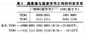
The DS18B20 temperature sensor's internal memory includes a scratchpad RAM and a nonvolatile, electrically erasable E2RAM that holds the high and low temperature triggers TH, TL and structure registers. The scratchpad memory contains 8 consecutive bytes, the first 2 bytes are the measured temperature information, the first byte is the lower 8 bits of the temperature, and the second byte is the upper 8 bits of the temperature. Among the upper 8 bits, the first 4 bits represent the positive (all "0") and negative (all "1") of the temperature; the 3rd and 4th bytes are the volatile copies of TH, TL; The bytes are volatile copies of the structure registers, which are refreshed on each power-on reset; the sixth, seventh, and eighth bytes are used for internal calculations; the ninth byte is redundant Check the bytes. Therefore, reading the contents of the temperature information byte can be converted into corresponding temperature values ​​accordingly. Table 1 lists the correspondence between temperature and temperature bytes.  Correspondence between temperature and temperature bytes
2. System hardware structure
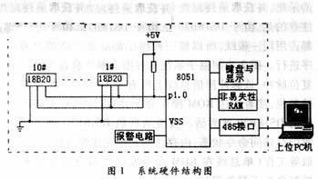
The system is divided into two parts: on-site temperature data acquisition and upper-level monitoring PC. Figure 1 is a block diagram of the system. It should be pointed out that the lower computer can work independently from the upper PC. The purpose of adding the upper computer is to make it easier to monitor and manage away from the scene. The on-site temperature acquisition part uses the 8051 single-chip microcomputer as the central processing unit, and 10 DS18B20 sensors are attached to the P1.0 port to detect the temperature of 10 points. Non-volatile RAM is used as a buffer for system temperature acquisition and operating parameters. The upper PC communicates with the on-site single-chip microprocessor through the RS485 communication interface, which comprehensively manages and controls the system, and can complete data recording and printing reports. The modules of the system are analyzed as follows:  2.1 DS18B20 and microcontroller interface circuit
The connection between the DS18B20 and the 8051 MCU is very simple. It only needs to connect the DS18B20 signal line to one I/O line of the MCU, and one I/O line can be connected to multiple DS18B20s to achieve single or multi-point temperature measurement. The DS18B20 can be powered in two ways: an external power supply and a parasitic power supply. The former requires an external power supply, and the positive and negative terminals of the power supply are respectively connected to the VDD and GND of the DS18B20. The latter uses a parasitic power supply to connect the VDD and GND of the DS18B20. When a high level occurs on the bus, the pull-up resistor supplies power; when the bus is low, the internal capacitor supplies power. This design uses this method because the external power supply method can enhance the anti-interference of the DS18B20. In practical applications, the distance between the sensor and the single-chip microcomputer is often in the range of tens of meters to several hundred meters. The parasitic capacitance of the transmission line also has a certain influence on the operation of the DS18B20. Therefore, the interface is often slightly modified to increase the driving capability of the chip and Reduce the impact of the transmission line capacitance effect and achieve long-distance transmission.
2.2 keyboard and display
The keyboard can be programmed to complete the following functions: calibrate the temperature value, display the temperature value of each channel periodically, display the temperature value of a certain channel separately, and set the upper and lower limit alarm values ​​for each channel. LEDs provide intuitive visual information to the user. At the work site, the user can determine the current working state of the system and the temperature value information sampled by the display data of the 6-digit LED.
2.3 alarm circuit
When the measured temperature value exceeds the preset upper and lower limits, the alarm circuit responds, and the buzzer sounds to inform the user of the abnormal temperature. Which of the sensor temperature values ​​exceeds the limit can be determined by software querying each DS18B20 internal alarm flag, and then the site temperature is adjusted to achieve temperature fluctuation control.
3. Software design and process
3.1 lower computer software
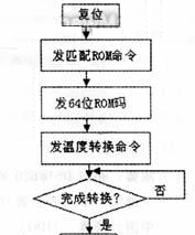
The system lower temperature measurement part software is written in MCS51 assembly language, mainly completes the read and write operations of DS18B20, realizes the real-time data acquisition, and obtains the final temperature value and sends it to the MCU memory. However, it should be noted that due to the single bus mode of the DS18B20, data reading and writing occupy the same line, so each operation must be performed in strict accordance with the timing. Figure 2 is a flow chart of the temperature measurement subsystem. The MCU first sends a reset pulse, which causes all DS18B20 chips on the signal line to be reset, and then sends a ROM operation command, so that the DS18B20 with the serial number code matching is activated. The activated DS18B20 enters the receive memory access command state, and the memory access command completes the temperature conversion, reading, etc. (the single bus stores the command and control commands before the ROM command is sent).
3.2 host computer software
The software of the system host computer is written in VC++6.0. The main functions include: real-time communication with the lower-level single-chip microcomputer; simulation display of the temperature curve of each collection point; preservation of the temperature data of each temperature measurement point; statistics of the average temperature value of each collection point; printing of temperature statistics reports at various points.  Program flow chart
4 Conclusion
The system has the following characteristics:
The structure is simple, the cost is low, and the maintenance is convenient.
By directly encoding the temperature data, it is possible to transmit temperature data using only a single cable, which is convenient for communication, long transmission distance and strong anti-interference.
The configuration is flexible, convenient, and easy to expand. The multi-channel lower temperature acquisition subsystem can be extended, and they are connected to the upper PC unit network through RS485 to form a multi-point temperature acquisition network. It is also possible to selectively increase or decrease the temperature sensor in each subsystem.
The work is stable and the temperature measurement accuracy is high. Experiments show that 24 DS18B20 temperature sensors are attached to a bus of up to 200 m, and the system can correctly collect temperature with a resolution of 0.5 °C.
Suitable for on-site temperature measurement in harsh environments, such as environmental control, equipment or process control, and temperature-measuring consumer electronics. It has a very attractive application prospect in a wide-range temperature multi-point monitoring system.
Mr Fog Vape,Mr Fog Max Pro,Mr Fog Max Pro Disposable Vape,Mr Fog Max Pro Vape
Nanning Nuoxin Technology Co., LTD , https://www.nx-vapes.com