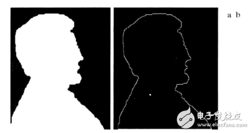
Figure 1 Binary image boundary extraction demonstration
As shown in Fig. 1, Fig. 1a is a simple binary image. After boundary extraction, an image as shown in Fig. 1b is formed, showing the outline of the white area.
2 boundary extraction algorithm With black extraction, the background is white, '1' for white and '0' for black.
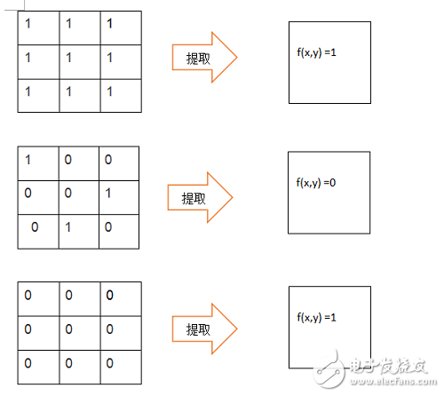
Figure 2 Binary image boundary extraction demonstration
We use 3x3 template for boundary extraction, so when 3x3 nine points are '1', the output is '1'. When all nine points are '0', the output is '1'. Is '0'.
3 FPGA binary image boundary extraction algorithm implementation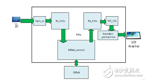
Figure 2 Binary image expansion FPGA module architecture
In Figure 2, we use a serial port to pass in a binary image.
FPGA source code:
/*
Module name: boundary_extracTIon.v
DescripTIon: binary image boundary extracTIon
*/
`TImescale 1ns/1ps
Module boundary_extraction(
Input clk, //pixel clk
Input rst_n,
Input hs_in,
Input vs_in,
Input [15:0] data_in,
Input data_in_en,
Output hs_out,
Output vs_out,
Output reg [15:0] data_out,
Output data_out_en
);
Wire [15:0] line0;
Wire [15:0] line1;
Wire [15:0] line2;
Reg [15:0] line0_data0;
Reg [15:0] line0_data1;
Reg [15:0] line0_data2;
Reg [15:0] line1_data0;
Reg [15:0] line1_data1;
Reg [15:0] line1_data2;
Reg [15:0] line2_data0;
Reg [15:0] line2_data1;
Reg [15:0] line2_data2;
Reg data_out_en0;
Reg data_out_en1;
Reg data_out_en2;
Reg hs_r0;
Reg hs_r1;
Reg hs_r2;
Reg vs_r0;
Reg vs_r1;
Reg vs_r2;
Wire[18:0] result_data;
Line3x3 line3x3_inst(
.clken(data_in_en),
.clock(clk),
.shiftin(data_in),
.shiftout(),
.taps0x(line0),
.taps1x(line1),
.taps2x(line2)
);
//------------------------------------------------ ------------------------------
// Form an image matrix of three multiplied by three
//------------------------------------------------ ------------------------------
Always @(posedge clk or negedge rst_n) begin
If(!rst_n) begin
Line0_data0 <= 16'b0;
Line0_data1 <= 16'b0;
Line0_data2 <= 16'b0;
Line1_data0 <= 16'b0;
Line1_data1 <= 16'b0;
Line1_data2 <= 16'b0;
Line2_data0 <= 16'b0;
Line2_data1 <= 16'b0;
Line2_data2 <= 16'b0;
Data_out_en0 <= 1'b0;
Data_out_en1 <= 1'b0;
Data_out_en2 <= 1'b0;
Hs_r0 <= 1'b0;
Hs_r1 <= 1'b0;
Hs_r2 <= 1'b0;
Vs_r0 <= 1'b0;
Vs_r1 <= 1'b0;
Vs_r2 <= 1'b0;
End
Else if(data_in_en) begin
Line0_data0 <= line0;
Line0_data1 <= line0_data0;
Line0_data2 <= line0_data1;
Line1_data0 <= line1;
Line1_data1 <= line1_data0;
Line1_data2 <= line1_data1;
Line2_data0 <= line2;
Line2_data1 <= line2_data0;
Line2_data2 <= line2_data1;
Data_out_en0 <= data_in_en;
Data_out_en1 <= data_out_en0;
Data_out_en2 <= data_out_en1;
Hs_r0 <= hs_in;
Hs_r1 <= hs_r0;
Hs_r2 <= hs_r1;
Vs_r0 <= vs_in;
Vs_r1 <= vs_r0;
Vs_r2 <= vs_r1;
End
End
//------------------------------------------------ -------------------
// line0_data0 line0_data1 line0_data2
// line1_data0 line1_data1 line1_data2
// line2_data0 line2_data1 line2_data2
//------------------------------------------------ --------------------
Always @(posedge clk or negedge rst_n) begin
If(!rst_n)
Data_out <= 16'h0000;
Else if(data_out_en1)
If((line0_data0 == 16'h0000) && (line0_data1 == 16'h0000) && (line0_data2 == 16'h0000) && (line1_data0 == 16'h0000) && (line1_data1 == 16'h0000) && (line1_data2 = = 16'h0000) && (line2_data0 == 16'h0000) && (line2_data1 == 16'h0000) && (line2_data2 == 16'h0000))
Data_out <= 16'hffff;
Else if((line0_data0 == 16'hffff) && (line0_data1 == 16'hffff) && (line0_data2 == 16'hffff) && (line1_data0 == 16'hffff) && (line1_data1 == 16'hffff) && (line1_data2 == 16'hffff) && (line2_data0 == 16'hffff) && (line2_data1 == 16'hffff) && (line2_data2 == 16'hffff))
Data_out <= 16'hffff;
Else
Data_out <= 16'h0000;
End
Endmodule
4 experimental results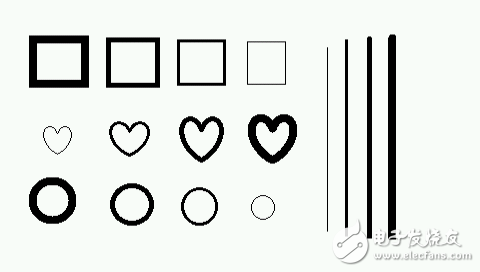
Figure 5 Experimental original picture 1

Figure 6 experiment original picture 2
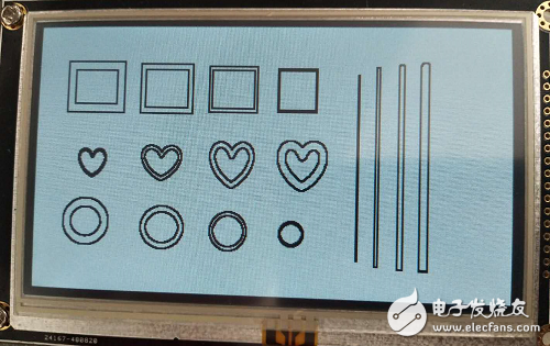
Figure 7 Experimental results Figure 1
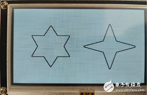
Figure 8 Experimental results Figure 2
Analysis of the results: In contrast to Figure 5 and Figure 7, the thicker lines are found out of the edge, only the thinnest one is not extracted and is thickened because the thinnest line has only three pixels when it is found out. The edges are black, and the black sides are connected together so the lines are thicker. Figure 6 and Figure 8 have no problems with edge lookup.
Small computer system interface (SCSI) is an independent processor standard for system level interfaces between computers and intelligent devices (hard disks, floppy drives, optical drives, printers, scanners, etc.). SCSI is an intelligent universal interface standard.
The last SCSI device in the SCSI chain uses a terminator, and the intermediate device does not need a terminator. Once the terminator is used by the intermediate device, the SCSI card cannot find the future SCSI device. If the last device does not use a terminator, SCSI will not work properly. Terminator is composed of resistors, located at the end of the SCSI bus, to reduce the mutual influence of the signal, maintain the constant voltage on the SCSI chain.
Most of the SCSI devices have built-in terminators and use a jumper to control on / off. The SCSI device is highly intelligent and can automatically control the terminator on / off. For example, if a hard disk is connected to a CD-ROM, the CD-ROM can work normally regardless of whether the terminator of the hard disk is on or off. However, when two hard disks are connected, the situation becomes more complicated. Before two Seagate hard disks are connected, one hard disk terminator must be off. Before a Seagate hard disk is connected to a quantum hard disk, a hard disk terminator can work normally regardless of whether it is on or off.
SCSI-90°DIP Section
ShenZhen Antenk Electronics Co,Ltd , http://www.coincellholder.com