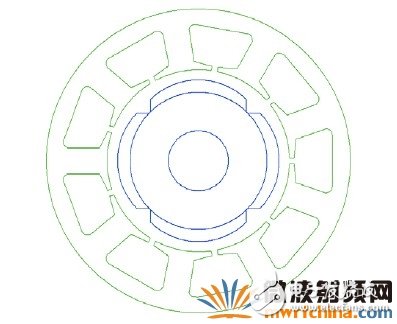
The motor is a 4-pole, 9-slot rare-earth permanent-magnet brushless motor. The actual design of the motor is not discussed here. Therefore, the specific parameters are not listed. They are only used as demonstration steps.
After setting all parameters of the motor, calculate the performance of the motor and obtain the characteristic parameters of the motor. The data of the RMXPRT and SIMPLORER will be compared later, so the torque and current curves of the motor are listed here.
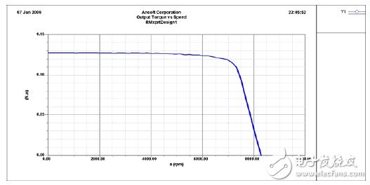
Torque-speed curve
Current-speed curve
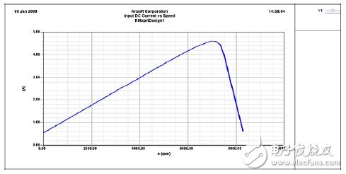
Note the torque and current values ​​at 6000 RPM, which are 124mNm and 4.18A, respectively. Note that the current limit value of 5.0A is set in this example, as is also the case in SIMPLORER.
3. Output the SIMPLORER model of RMXPRT. The steps are shown below
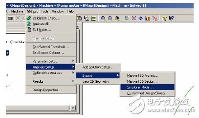
4. The operation of the RMXPRT is completed here, and the center of the output phase A of the model phase is aligned with the center of the magnetic pole. This is very important. In RMXPRT, the alignment is automatic. In MAXWELL, users must do it themselves.
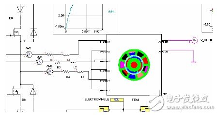
5. Import the previously created RMXPRT model in SIMPLORER,
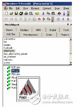
The path is MODELAGENTADDONINTERFACESRMXPRT
6. Drag the RMX-LINK icon in the figure above to the SIMPLORERSCHEMATIC window and double-click the icon
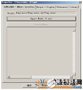
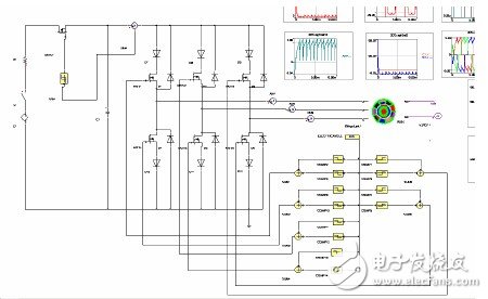
The motor IMPORTMODEL specifies the path of the SIMPLORER model of RMXPRT in the path. In this way, the SIMPLORER model of the motor is imported, and the RMX-LINK icon becomes the actual shape of the motor. The following is the inverter model.
7. The inverter is composed of MOSFETs. For simplicity, the MOSFET uses a system-level component model.
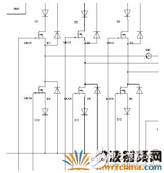
8. MOSFET drive circuit
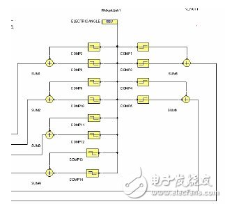
This drive actually shows the timing of turning on the 3-phase winding of the motor using the SIMPLORER module. The 1-phase signal is a combination of positive and negative pulses.
The composition-driven approach provided by SIMPLORER is varied, and everyone can try different ways.
9. Add current limiting circuit
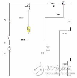
This is a current hysteresis control, and the current setting is the same as in RMXPRT.
Set the motor speed to 6000RPM.
10. Here, the model of co-simulation is fully established. Because RMXPRT is a computational software for the magnetic circuit method, the co-simulation process ends in only a few seconds. To understand possible setup errors, first look at the MOSFET's switching signal is normal.
A-phase MOSFET switching signal
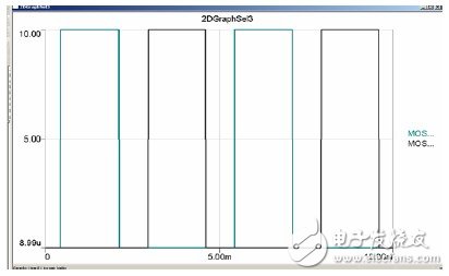
This switch signal is normal.
11. Simulation results
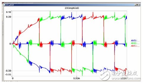
Phase current
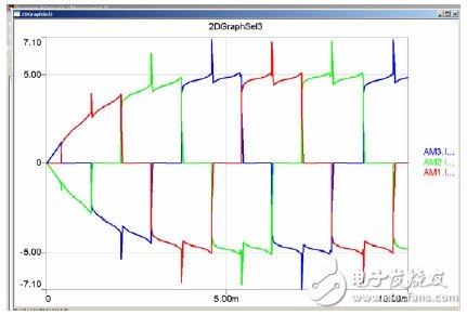
Motor current
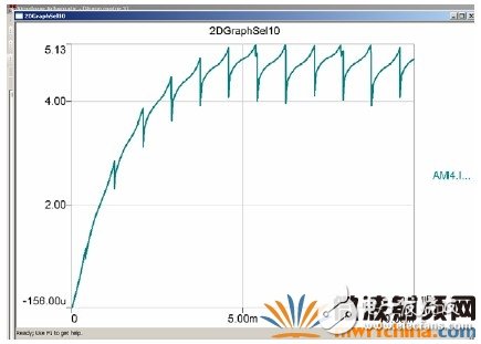
Motor current 4.76A.
Torque
The average torque is 127mNm.
Here, the co-simulation of RMXPRT and SIMPLORER is completed. The following is a simulation example of MAXWELL and SIMPLORER.
12. Establish the MAXWELL model
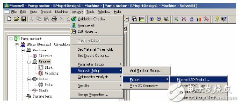
Execute the EXPORT command in RMXPRT to generate the MAXWELL model. The steps are:
RMXPRTANALYSISSETUPEXPORTMAXWELL2DMODEL specifies the model file address
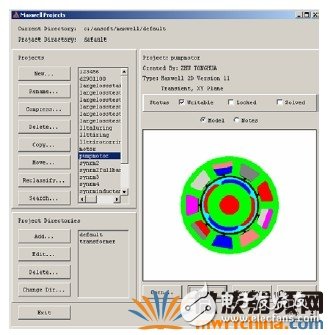
Imported MAXWELL Project Files
13. Material property settings
The material properties are set according to the actual situation. In order to compare with RMXPRT, it is set to be the same as RM. MAXWELL also needs to set special CORELOSS. It can use the actual value of the material.
14. Alignment of rotor and stator
As mentioned earlier, the center of the rotor magnet is aligned with the center of the winding. This facilitates the setting of the timing of the excitation. In this example, the rotor is rotated 70 degrees counterclockwise.
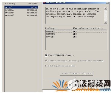
15. External circuit settings
The imported RMXPRT model has its winding object name already set. What we need to do is to tell the MAXWELL the polarity of the winding and the connection method. Set 33 turns per phase, 3 coils per phase, each phase resistance is 0.15 ohm, leakage inductance 1E -5H.
16. Boundary Condition Settings
Set the vector potential A=0 boundary at the edge of the stator
17. Set Grid, BAND, Mechanical Properties,
For simplicity, this example uses an initial mesh. Set the BAND object to BAND. Because the joint simulation will be performed later, the motion setting will be covered by the setting of SIMPLORER. At the same time, since it is a uniform motion, the moment of inertia is not set. If it is a simulation start-up process, you can fill in the moment of inertia calculated by RMXPRT.
18. Set USECONTROLPROGRAM, controlled by TDSLINK_TCP.EXE.
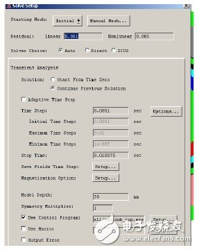
At the same time set the motor length to 30 mm, set the step length and simulation time.
19. Import MAXWELL Models into SIMPLORER
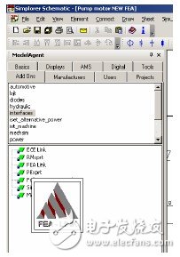
MODELAGENTADDONINTERFACESFEALINK
Drag the FEALINK icon into the SIMPLORERSCHEMATIC window, double-click the icon, and click QUERY. If the model is set up correctly, it can be simulated and it will be blue, otherwise it will be red.
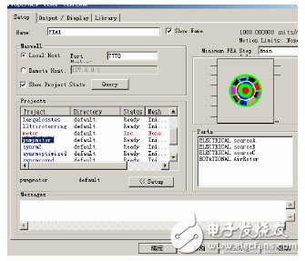
20. Because the MAXWELL model and the RMX PRT model are models of the same motor, the external circuit of the SIMPLORER is the same, as long as the MAXWELL model is replaced by the RMXPRT model.
21. Set SIMPLORER simulation parameters, this is nothing to say, set according to the actual situation.
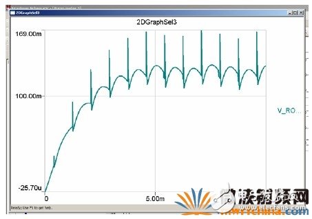
22. Set the motor speed 6000RPM, CCW direction. The speed of the motor is controlled by V_ROTB1, which is an angular speed setting module.
Each phase resistance and leakage inductance are all set.
23. The external circuit setup is the same as RMXPRT.
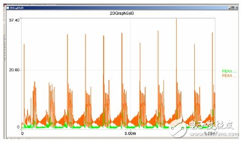
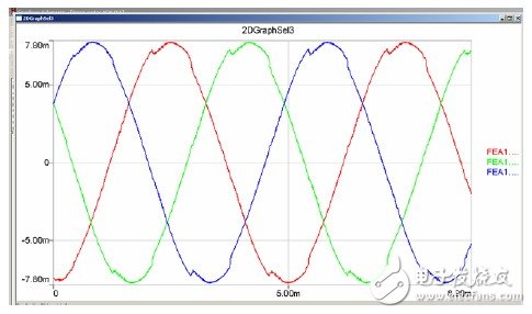
24. Simulation results
Phase current
Motor current
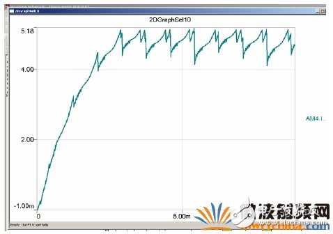
Current 4.73A.
Torque
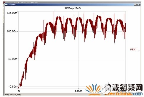
Torque 113mNm.
Iron consumption
The average iron loss is 4.6W.
FLUXLINKAGE
The simulation time is about one hour.
The current of MAXWELL+SIMPLORER is very close to RMXPRT+SIMPLORER because MAXWELL uses the resistance data of RMXPRT. There is a 12% difference in torque, which may be due to the fact that the 2D MAXWELL did not consider the end contribution.
GALOCE offers alloy steel low profile ring torsion Load Cell; can replacement HBM RTN model load cell, IP 67 (hermetically sealed) load cell is suitable for high accuracy hoppers, platforms and pallet scales. It has an integrated static overload protection. Due to its design and protection this is extremely suitable for the food industry, Process control, Bulk handling applications, Food weighing machines, Platform applications, Hoppers, Batch weighing, Silo applications, Belt scale applications.
Torsion Load Cell,Ring Torsion Load Cell,Torsion Type Load Cell,Ring torsion load cells
GALOCE (XI'AN) M&C TECHNOLOGY CO., LTD. , https://www.galoce-meas.com