Working principle: The amplifier circuit adopts LM358 integrated operational amplifier. In order to prevent the nonlinear error caused by too high single-stage amplification, the amplifier circuit adopts two-stage amplification, as shown in Figure 5.1. The previous stage is about 10 times, the latter stage. About 3 times. The temperature changes from 0 to 100 degrees. When the temperature rises, the resistance of Pt100 becomes larger, the differential signal of the input amplifier circuit becomes larger, and the output voltage Av of the amplifier circuit rises accordingly.
R2, R3, R4 and Pt100 form the sensor measurement bridge. In order to ensure the stability of the bridge output voltage signal, the input voltage of the bridge is stabilized to 2.5V through the TL431. The differential signal obtained from the bridge is amplified by a two-stage op amp and input to the microcontroller. One bridge of the bridge uses an adjustable resistor R3. By adjusting R3, the differential voltage signal input to the op amp can be adjusted, usually used to adjust the zero point.
Note: Although the bridge part has been regulated by TL431, the voltage VCC of the whole module must be stable. Otherwise, as the VCC fluctuates, the operating voltage of the op amp LM358 fluctuates, and the output voltage Av fluctuates, eventually resulting in The result of the A/D conversion fluctuates and the measurement results jump up and down.

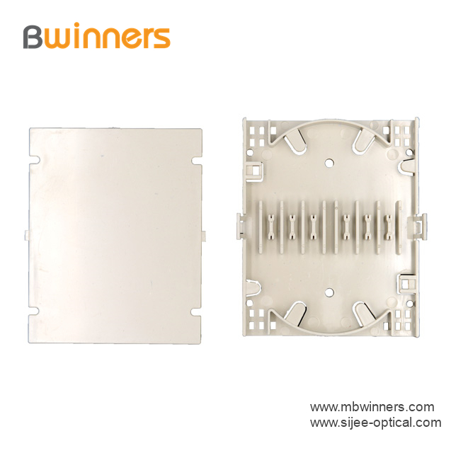
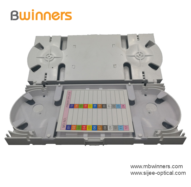
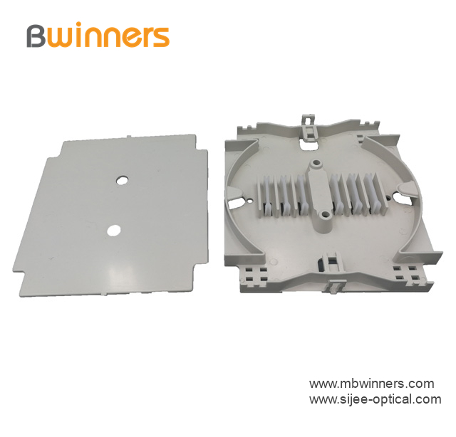
FTTH Fiber Optic Splice Tray is designed to provide a place to store the fiber cables and splices and prevent them from becoming damaged or being misplaced. It is also called a splice enclosure or splice organizer. This device does not contain any technical functions, and the design is simple. Also, Fiber Optic Tray has a very low price for people to afford. However, the importance of fiber splice tray for protecting fibers is significant. And the skills needed for using a fiber splice tray is not as simple as you think.
Made by industrial high-quality ABS plastic, Fiber Optic Cable Tray is provided to place the fiber splice points and pre-terminated for fiber connectivity. The splice tray expands fiber splice capabilities as well as provides the splicing location for fiber optic cables. It can be put into the fiber distribution frame, fiber splice closure, optic terminal box, etc. Sijee offers different shapes of fiber splice tray with or without termination function. Fiber Optic Tray, Fusion Splice Box, Fiber Optic Cable Tray, Splice Tray Optic Fiber are available.
Applications:
Fiber splice trays are usually placed in the middle of a route where cables are required to be joined or at the termination and patch panel points at the end of the cable runs. Also, splices can be placed in a splice tray which is then placed inside a splice closure for OSP (outside plant) installations or a patch panel box for premises applications. As for indoor application, fiber splice trays are often integrated into patch panels to provide for connections to the fibers.


Fiber Optic Tray,Fusion Splice Box,Fiber Optic Cable Tray,Splice Tray Optic Fiber
Sijee Optical Communication Technology Co.,Ltd , https://www.sijee-optical.com