An all-electric vehicle without an internal combustion engine requires a safe, cost-effective and high-capacity energy storage system. Efficient software algorithms, powerful microcontrollers and high-efficiency motors make the most of existing energy sources, and high integration helps achieve a leaner and lower cost motor control system. Designed for hybrid and electric vehicles, a new generation of highly integrated MCUs includes timing structures that generate motor control signals and a variety of I/O ports and interfaces.
Figure 1 shows a broad classification of hybrid and electric vehicles. The core element of hybrid and electric vehicles is the motor in the transmission system, which is deployed in a hybrid vehicle with a conventional internal combustion engine and as an independent source of kinetic energy in an electric vehicle. Selecting the motor requires careful analysis of size, weight, reliability, durability, required torque and overall efficiency.
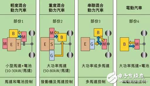
Figure 1: Classification diagram of hybrid and electric vehicles.
There are two basic types of motors that are suitable. One is an asynchronous motor that is durable and reasonably priced because they do not require magnets made from rare earth elements. Its characteristic parameters can be controlled by software algorithms and do not require maintenance. This motor is slightly less efficient than a synchronous motor and has a lower torque at start-up. The disadvantage is that the efficiency is slightly lower, about 90%, and the weight is heavier.
Another suitable motor is a permanent magnet synchronous motor (PMSM) with high torque, tight dimensions and high efficiency of nearly 94%. Synchronous motors are costly due to the need to use permanent magnets made of rare earth elements. Brushless versions of asynchronous motors and permanent magnet synchronous motors have no problem with brush loss. Permanent magnet synchronous motors offer better size/torque ratios and higher efficiency and are the first choice for electric and hybrid automotive transmission systems.
control
As mentioned earlier, both motors have a brushless version. Although this brushless motor requires more rectification, it provides safe and efficient control, which is fundamental and primary in the transmission system. The challenge now is to achieve the perfect balance of motors, power electronics, control units (microcontrollers) and control software. The algorithms used must be adapted to the respective motor and application, allowing the electronic controller to optimize motor rectification at all times. Failure to properly adapt can lead to adverse effects, such as irregular execution and excessive noise, which can have a certain negative impact on efficiency. Motor control includes various control algorithms for different applications.
Sensor-based rotor position sensing can be implemented by a variety of sensing systems. In general, detecting the position of the rotor is critical to precise motor control. As an important component, rotor position sensors have a significant impact on the performance and efficiency of the motor system. The Hall position sensor is based on the Hall effect and induces a voltage by changing the magnetic field around the current carrying conductor. With the help of the rotor magnet ring and the sensor device attached to the rotor, the Hall effect sensor is a convenient and inexpensive method for detecting angles. The greater the number of poles and Hall components, the higher the resolution and accuracy, and the more susceptible to magnetic field interference.
Incremental encoders are a common sensor that is used in a wide range of designs, with mechanical and optical scanning characteristics to determine the current angular position. When measuring angles, the incremental encoder must be based on a zero position or reference position. For a microcontroller, the actual angle measurement involves only detecting the direction of rotation and the operational pulse divergence. The angular velocity can be calculated by simply measuring the time interval between two pulses. The non-inductance of electromagnetic interference is very beneficial; on the contrary, any mechanical friction loss and susceptibility to dirt are disadvantageous in optical systems.
Decomposer
The resolver is a rugged sensor commonly used in the automotive industry, immune to magnetic field disturbances and dirt, and is immune to frictional losses during angle detection. It consists of a wheel permanently attached to the motor shaft (motor rotator) and an annular stator permanently attached to the motor casing. The stator includes at least one excitation coil and two sensor coils. Higher resolution can be achieved by increasing the number of pole pairs.
Figure 2 shows the resolver. The excitation coil is equipped with an analog sinusoidal signal. The analog signal is transmitted to the two sensor coils via magnetic coupling (induction) and placed at 90 degrees to each other. Evaluation of the analog sine and cosine signals returned by the resolver requires a shaft angle digitizer (RDC) that is used to determine the angular position and velocity from the simulated data.
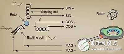
Figure 2: Decomposer schematic and mechanical structure.
Decomposers may not be superior in performance and accuracy to other competing technologies, but they are more durable and provide better protection in environments such as dirt and extreme temperatures. Even in the stationary state, it can detect the absolute position of the motor at any time, while incremental encoders and Hall sensors cannot perform this function.
REMOTE CONTROL SOCKET
Important Safeguards
When using any electrical appliance, in order to reduce the risk of fire, electric shock and/or injury to persons, basic safety precautions should always be follow8d. including:
• The appliance is for household and indoor use only.
• Before plugging in. check that the voitage on the rating label is the same as the mains supply.
• To protect against electric shock, do not immerse any part of the product in water or other liquid.
• This socket is intended for use by competent adults only and children should be supervised at all times.
• Do not use the socket for other than its intended use.
• This socket can be used by children aged from 8 years arxl above and persons with reduced physical, sensory or mental capabilities or lack of experience and knowledge if they have been given supervision or instruction concerning use of the appliance in a safe way and understand the hazards involved. Children shall not p<ay with the appliance Cleaning and user maintenance shall M be made by children without supervision.
• Children of less than 3 years should be kept away unless continuously supervised.
Children from 3 years and less than 8 years shall only switch on/off the appliance provided that it has been placed or installed in its intended normal operating position and they have been supervision or instruction concerning use of the appliance in a safe way and understand the hazards involved. Children aged from 3 years and less than 8 years shall not plug in. regulate and clean the appliance or perform user maintenance.
• Don't use this socket in the immediate surroundings of a bath, a shower or a swimming pool.
• In case of malfunction, do not try to repair the socket yourself, it may result in a fire hazard or electric shock
Do Not Exceed Maximum a680W
Place the LR44 batteries provided into the compartment in the back of the Remote Control, please insert as sho*/m in the back of the compartment to ensure the polarity is correct.
Programming Instructions
• Plug the Remoce Socket$($)lnto the wall socket(s) and switch on the mams supply, the red LED will flash every second.
• If the LED is not flashing press & hold the manual ON/OFF button for 5 seconds until it Hashes
•Press any ON switch on the Remote Control for approximately 2 seconds and the Remote Socket(s) learn the code. The LED will stop flashing top confirm the codehas been accepted.
• Any number of Remote Sockets can be programmed to one Remote Control ON button to create multiple switching.
• To programme o<her Remote Sockets on different Remote Control ON buttons repeat the prevous steps
• If the mains supply is turned off the Remote Sockets v/ill lose their code and it wil be necessary to re-pcogramme.
Operation:
• Plug your appliance(s) into the Remote Socket(s)
• Press the programmed ON or OFF button on the Remote Control to control the Remote Socket.
♦ The Remote Sockets can also be operated manually using its ON/OFF Button Trouble shooting
If a Remote Socket does not react to the Remote Control please check the followng:
♦ Low battery in tbo Remote Control
• Distance too large between the remote control and the recerver (ensure the range distance is no more than 20 clear Metres) and free from obstacle that may reduce the distance.
• If programming has not been successful, tum the power off and back on then follow the programming steps above.
How to decode
• Press the manual ONX)FF button for 5 seconds until the red LED flashes once per
second to confirm de-coding is successful
♦ Press the ALL OFF switch on the Remote Control for more than 3 seconds, the LED
flashes once per second to confirm (decoding successful.
Voltage: 240V-/50HZ
Max power rating: 3680W max.
Remote frequency:
Remote range:
Battery Type:
433.92MHz
230 Metres
Button Cell 2x1.5V LR44 =
Please check with your local waste management service authority regarding regulations for the safe disposal of the batteries. The batteries should never be placed G municipal waste.
Use a battery d^posal facility if available
M
For eioctncal products sold within the European Community. At the end of the electrical products useful life, it should not be disposed of wth household waste. Please recycle faaMies exist. Check with your Local Authonty or retailer for recycling advice.
C€
Remote Control Plug Socket,Remote Controlled Mains Outlet,Remote Control Plug Adapters,Remote Control Sockets,Remote & Smart Controlled Sockets,Electric Sockets Plus Remote Control
NINGBO COWELL ELECTRONICS & TECHNOLOGY CO., LTD , https://www.cowellsockets.com