Abstract: Aiming at the demand of digital network video surveillance system, a video server based on MPEG-4 network is designed. The MPG440-based MPEG-4 real-time video compression card is used to compress the collected audio and video data, and the loop queue is used to compress the audio and video data. At the same time, the multi-threading technology and the transmission mechanism are used to solve the transmission of the network data, thereby effectively restraining the picture from being unclear. , audio and video are not synchronized, mosaic and other phenomena, to ensure the real-time and synchronization of audio and video during customer monitoring. The experiment proves that the solution is economical and efficient, and can be applied to a variety of occasions requiring audio and video monitoring.
Keywords: embedded system; Linux; S3C2410; network video surveillance
With the development of computer technology and network technology, there have been rapid changes in the field of single-chip microcomputers, such as high-speed signal processors, SoC system-on-chip and other new technologies and new applications have sprung up. In real life, I often encounter such problems: how to remotely monitor the temperature and humidity of the computer room; how to master the safety situation at home, all of which need to apply a small power consumption, 24 hours of uninterrupted work, small size Remote video surveillance system.
Aiming at the practical application requirements of network video surveillance equipment, combined with image acquisition compression coding, embedded system and network technology, an embedded network video surveillance system is designed to realize video data collection and compression. network transmission. The system is based on S3C2410 ARM920T chip and embedded Linux operating system. It uses USB camera to capture video. It is compressed and encoded by MPG440 chip. The system is directly connected to the network. Users can view remote video images using standard web browser and streaming media player. .
1 System overall design The overall system design includes hardware design and software design. The hardware design module mainly includes a micro-controller module, a compression coding module, and a network interface module. The microcontroller module is mainly composed of a main control chip, DATAFLASH and SDRAM. Among them, the main control chip is the core of the entire control system, which is responsible for the scheduling of the entire system. The embedded Linux kernel and its file system, application software and system configuration files are solidified in DATAFLASH. SDRAM is used as memory for system operation. The compression coding module is composed of a video data acquisition chip, an MPEG-4 compression coding chip, and an SDRAM, and is responsible for converting a video stream into an MPEG-4 code stream. The network interface module mainly cooperates with the main control chip to transmit the MPEG-4 code stream. When the system boots, the microcontroller loads the Linux kernel into SDRAM and the system boots from SDRAM. After the system is started, the microcontroller controls the MPEG-4 encoding module to work.
The software design part mainly includes embedded Linux transplantation, video acquisition and MPEG-4 compression coding module, JRTPLIB network transmission module and MPEG-4 decoding program. The embedded Lin-ux system is stored in the DATAFLASH controlled by the S3C2410, which is responsible for the scheduling of the entire system software. The MPEG-4 compression coding module is mainly responsible for compressing the collected video stream into an MPEG-4 data stream. The JRTPLIB network transmission module is mainly responsible for the related settings of MPEG-4 video stream transmission and control. The MPEG-4 decoding program is primarily responsible for decoding MPEG-4 data streams obtained over the network.
2 hardware system design The hardware platform of the system uses Samsung's processor S3C2410. The processor integrates ARM's ARM920T processor core 32-bit microcontroller with rich resources: independent 16 kB instruction cache and 16 kB data cache, LCD controller, RAM controller, NAND flash controller, 3 UART, 4 DMA, 4 Timer with PWM, parallel I/O port, 8 10-bit ADC, TouchScreen interface, I2C interface, I2S interface, 2 USB interface controllers, 2 SPI, highest frequency Up to 203 MHz. On the basis of the rich resources of the processor, related configuration and extension are also carried out. The platform is configured with 16 MB, 16-bit FLASH and 64 MB, 32-bit SDRAM. An Ethernet port is extended by the Ethernet controller chip DM9000, and a HOST and USB interface are also introduced. An external camera with a USB interface is connected to the USB interface. The hardware system structure is shown in Figure 1. 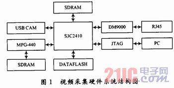
3 software system design Linux has a small kernel, high efficiency, open source code, the kernel directly provides network support and so on. However, the hardware resources of the embedded system are limited, so Linux cannot be directly used as the operating system. The system should be customized by configuring the kernel, cutting the shell and the embedded C library for specific applications, so that the whole system can be stored to a smaller capacity. In FLASH. Linux's dynamic module loading makes Linux cuts extremely convenient, and highly modular components make it easy to add. The embedded Linux system is mainly composed of four parts: the file that boots the kernel boot.
(bootloader), Linux kernel file (kernel), virtual disk file (ramdisk), user space file (user). They are placed in four partition modules within DATAFLASH. According to the specific functions of different modules, different file systems, such as: bootloader, kernel, ramdisk, etc., do not need to be dynamically changed after the migration, use a more space-saving ROM-FS read-only file system; some of the user modules can be dynamically updated The configuration file, etc., requires a lot of read and write operations, so the JFFS2 file system that supports dynamic erasing is used. Based on the above advantages of Linux, the implemented platform uses the operating system μclinux. Usually the development of embedded system software uses cross-compilation debugging. The host is usually an Intel processor, and the target board is S3C2410 as shown in Figure 1. Therefore, the program needs to use a compiler-specific compiler to generate code that can run on the corresponding platform. For embedded Linux, the Linux system should be installed on the host PC, and then the development environment for cross-compilation and debugging should be established on the host. The highly portable C language is used to write the video capture program on the host machine, and then the cross-compilation debugging tool is used to compile the link to generate the executable code, and finally transplanted to the target platform.
The Linux porting technology has matured and will not be elaborated here. It mainly introduces the programming of USB camera driver, V4L-based video capture module and JRTPLIB network transmission module.
3.1 USB Camera Driver After setting up the development environment of embedded Linux, the first step is to install and drive the USB camera.
Under Linux, device drivers can be thought of as the interface between the Linux kernel and external devices. The device driver shields the application from the details of the hardware implementation, allowing the application to operate the external device as if it were a normal file, and can use the same, standard system call interface functions in the file to open the hardware device. Shutdown, read/write, and I/O control operations, and the main task of the driver is to implement the calling functions of these systems.
Video4Linux (V4L) is a kernel driver for video devices in Linux. It is a set of interface functions for video device application programming. For the USB port camera, the driver needs to provide the basic I / O operation interface functions open, read, write, close to achieve. When the application makes a system call operation on the device file, the Linux kernel will access the function provided by the driver through the file-operations structure, and drive the USB port digital camera on the system platform. First, the USB controller driver module is statically compiled into the kernel. To enable the USB interface in the platform, and then use the insmode to dynamically load its driver module when you need to use the camera to capture, so that the camera can work normally.
After determining that the USB camera is properly driven, the next step is to write a video capture program using the API function set provided by Video4Linux.
3.2 V4L-based video capture module Under Linux, all peripherals are treated as a special file called a device file. The system calls the interface between the kernel and the application, while the device driver is the interface between the kernel and the peripheral. He completes the initialization and release of the device, functions such as various operations and interrupt handling of the device file, and shields the application from the details of the peripheral hardware, allowing the application to operate on the peripheral like a normal file. The video acquisition process under Linux is shown in Figure 2. 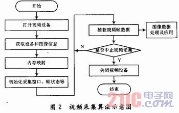
The video subsystem Video4Linux in Linux provides a unified API for video applications, and video applications can operate a variety of different video capture devices through standard system calls. Video4Linux registers the video device file with the virtual file system, and the application accesses the video device by operating the video device file.
Here, the program is mainly designed for video capture of the device file /dev/video.
The main functions used are:
Camera_open(): Used to open the video device file. You need to declare a device file of type video_device before using it.
Camera_get_capability(): Get information about the device file by calling the ioctl() function and store it in the video_capability structure.
Camera_get_picture(): Get information about the image by calling the ioctl() function and store it in the video_picture structure.
Camera_close(): Used to close the device file.
Camera_grab_image(): used to capture images. Use mmap mode to directly map the device file /dev/video0 to memory, speed up file I/O operations, and enable multiple threads to share data.
The rest are related functions such as device initialization, parameter devices, etc., which are not detailed here.
3.3 After the video compression coding module acquires the image data, it can be directly output to the FrameBuffer for display. Since the system wants to transmit the collected video effects through the network, the original image data should be compression-coded before transmission. This selects the MPG440 chip of Yingjia Company to implement the MPEG-4 video codec solution. Compared with other standards, MPEG-4 has a higher compression ratio, saves storage space, and has better image quality. It is especially suitable for transmitting video under low bandwidth conditions and maintaining image quality. After the video stream is compression-encoded, the next step is to implement the function of the network transmission part.
3.4 JRTPLIB network transmission module Streaming media refers to continuous time-based media transmitted by streaming technology in the network. RTP is the best solution to solve the problem of real-time streaming media. JRTPLIB is an object-oriented RTP library. Following the RFCl889 design, the following describes how to use the RTP protocol for real-time streaming media programming on the Linux platform.
3.4.1 Initialization Before using JRTPLIB for real-time streaming data transfer, you should first generate an instance of the RTPSession class to represent the RTP session, and then call the Create() method to initialize it. The Create() method of the RTPSession class has only one parameter that indicates the port number used for this RTP session.
3.4.2 Data Transmission After the RTP session is successfully established, the real-time transmission of streaming data can begin. First, you need to set the destination address for data transmission. The RTP protocol allows multiple destination addresses for the same session. This can be done by calling the AddDestination(), DeleteDestination(), and ClearDestinations() methods of the RTPSession class. After all the target addresses are specified, the SendPacket() method of the RTPSession class can be called to send streaming media data to all destination addresses.
3.4.3 Data Reception For the streaming data receiving end, you first need to call the PollData() method to receive the sent RTP or RTCP datagram. Since multiple participants (sources) are allowed in the same RTP session, all sources can be traversed by calling the GotoFirstSource() and GotoNextSource() methods, or by calling the GotoFisstSourceWithDat() and Got-oNextSourceWithData() methods. Traverse the sources that carry the data. After detecting a valid data source from the RTP session, the RTP datagram can be extracted from the RTPSession class by the Get-NextPacket() method. After the received RTP datagram is processed, it should be released in time.
JRTPLIB defines three receiving modules for RTP datagrams. The following receiving modes can be set by calling the SetReeeiveMode() method of the RTPSession class:
RECEIVEMODE_ALL: The default receiving mode, all arriving RTP datagrams will be accepted;
RECEIVEMODE_IGNORESOME: All arriving RTP datagrams will be accepted except for certain senders, and the rejected sender list can be set by calling AddTo-IgnoreList(), DeleteFromlgnoreList() and ClearIgnoreList() methods.
RECEIVEMODE_ACCEPTSOME: All arriving RTP datagrams will be rejected except for certain senders, and the accepted sender list can be set by calling the AddTo-AcceptList(), DeleteFromAcceptList and ClearAcceptList() methods.
3.4.4 Control Information JRTPLIB is a highly encapsulated RTP library. As long as the PollData() or SendPacket() method is successfully called, JRTPLIB can automatically process the RTCP datagram and send it when needed. RTCP datagrams to ensure the correctness of the entire RTP session. In the system, use the method provided by the RTPSessionJRTPLIB class library to implement the underlying RTP/RTCP operation, and encapsulate it in the CrtpTransmitter class, which inherits from the MediaSink class, receives the corresponding media frame data, and uses the RTPSession class library. The operation sends the data to the network.
4 Conclusion Because the system is based on S3C2410 platform and Linux operating system, using Video4Linux design acquisition program, using MPEG-4 compression coding, real-time streaming media transmission technology to achieve network transmission, so the cost of hardware and software is low, small size, the whole system It has the characteristics of stable and reliable, easy to install, and the monitoring distance can be extended with the network extension, which has a good development and application prospect. Scalable applications in industrial control, video conferencing systems, video telephony, remote monitoring systems and many other areas.
This article refers to the address: http://
Touch sensitive sensor has humanized design. The switch can automatically disconnect when electricity breaks and it will be in the OFF station when electricity comes back. Touch control ensures longer service life than mechanical switch. New imported IC processor for nice sensitivity and stable performance.
Description of Touch Sensitive Sensor
Item: Touch Sensitive Sensor
Size: 12mm*19.5mm
Voltage: 3V
Function: on/off, dimming
Standby Power: <0.1W
MOQ: 1000pcs

FAQ:
Q1. Can I have a sample order for led light?
A: Yes, we welcome sample order to test and check quality. Mixed samples are acceptable.
Q2. What about the lead time?
A:Sample needs 3-5 days, mass production time needs 1-2 weeks for order quantity more than 1000pcs
Q3. Do you have any MOQ limit for led light order?
A: Low MOQ, 1pc for sample checking is available
Q4. How do you ship the goods and how long does it take to arrive?
A: We usually ship by DHL, UPS, FedEx or TNT. It usually takes 3-5 days to arrive. Airline and sea shipping also optional.
Touch Sensitive Sensor
Touch Sensitive Sensor,Cabinet Lighting Touch Sensor,Touch Sensitive Pir Sensor,Touch Ir Sensor
Shenzhen Jedver Smart Lighting Co., Ltd. , http://www.jederwell.com