The thermal resistance, that is, the resistance encountered by heat in the heat flow path, reflects the amount of heat transfer between the medium or medium, indicating the temperature rise caused by 1 W of heat, in °C/W or K/W. An analogy can be used to explain that if the heat is equivalent to the current and the temperature difference is equivalent to the voltage, the thermal resistance is equivalent to the resistance. Generally, in the application of the LED device, the structural thermal resistance distribution is the thermal resistance of the chip substrate, the bonding layer between the substrate and the LED holder, the LED holder, the external heat sink of the led device , and the free space, and the thermal resistance channels are connected in series.
As a new energy-saving lamps led lighting only during illumination convert 30-40% of the electrical energy into light, all the rest becomes heat, causes the presence of heat resistance must pay attention to the LED package device. Generally, the higher the power of the LED, the more obvious the thermal effect of the LED, and the problems caused by the thermal effect are also highlighted, for example, the red shift phenomenon of the high temperature of the chip; the permanent damage of the chip due to the excessive junction temperature; the luminous efficiency of the phosphor layer is lowered. And accelerated aging; color temperature drift phenomenon; mechanical failure caused by thermal stress. These directly affect the LED's luminous efficiency, wavelength, forward voltage drop and lifetime. LED heat dissipation has become a huge bottleneck in the development of lamps.
How should I evaluate the heat dissipation level of LED package devices?
Application examples
1. Package device thermal resistance test
(1) Test method one:
In the process of testing the thermal resistance, the general heat dissipation path of the packaged product is a chip-solid layer-support or substrate-solder paste-assisted test substrate-thermal conductive connecting material.
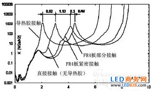
Side structure and heat dissipation path
According to the test, the thermal resistance curve as shown below can be obtained, and the total thermal resistance (the entire heat dissipation path) of the test product can be read as 7.377 K/W. The thermal resistance tested by this method needs to determine the thermal resistance delamination in the curve according to the structure of the test sample, and obtain the accurate thermal resistance of the packaged device. This method is more suitable for SMD package devices.
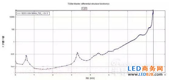
Thermal resistance curve
Automotive Wiring Harness Protection Sleeve
Automotive Wiring Harness Protection Sleeve,Braided Heat Shrink Tubing,Wear Resistant Heat Shrink Tubing
Shenzhen Huiyunhai Tech.Co., Ltd. , https://www.cablesleevefactory.com