The forum is some of the great by-products of the Internet. They provide a simple way for humans to share ideas, ask questions, and discuss incredible topics.
We created the TI E2ETM community as a place where engineers can directly consult engineers who design TI devices for technical issues related to these devices. As an application engineer in the TI motor drive group, I often check the contents of the motor drive forum to solve various problems and comment on the discussion.
In this five-part blog series, the author will focus on some of the most frequently asked questions I have seen in the TI E2E forum and focus on how to get started.
Many of the questions on the forum can be solved by looking at the device product manual. The navigation mark with the words "Reading Manual" can be passed by many names in different industries, but its meaning is exactly the same. Although this sounds simple, knowing how to navigate the product manual will allow you to quickly find the information you need. So let's take a look at some of the more important parts of TI's motor drive product specification.

Home
The front page of this data sheet gives you an idea of ​​what the device can do and whether it is suitable for your system. It includes the device name, description, characteristics, a simple chart, and several other key columns:
Features: Highlights of the features available in this device. This section usually contains information about the operating range, device integration, protection functions, and various other column items (Figure 1).
Application: This is a list of common applications designed for this application. It is not a comprehensive list.
Description: A detailed summary of the device and its functions.
Device Information: Information related to the various packages used in the device (Figure 2).
Charts: These charts usually show a simplified block diagram of the device or highlight one of its main features (Figure 3).
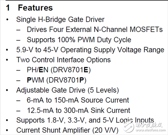
Figure 1: Typical characteristics section
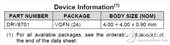
Figure 2: Device Information
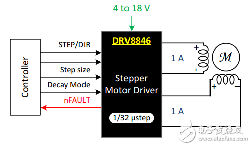
Figure 3: Block diagram
Recommended operating conditions
The recommended operating conditions (Figure 4) are key limitations (the device will only work within these limits). Important items that should be noted in the motor drive product manual include the following:
Power supply voltage range.
Low dropout regulator (LDO) external load current.
Output current capability.
Maximum input frequency.
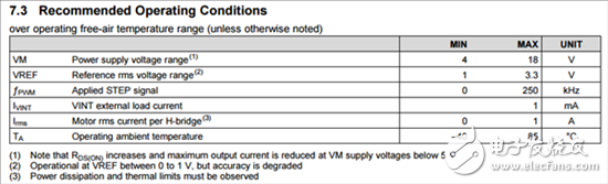
Figure 4: Recommended operating conditions
Electrical characteristics
The electrical characteristics are described using the device's parameters and specification tables. This includes information related to regulator output voltage, logic voltage level, timing specifications, current capability, RDS(on), and protection functions.
Two important technical parameters are the RDS(on) of the metal oxide semiconductor field effect transistor (MOSFET) and the parameters of the protection circuit. RDS(on) is the main limiting factor in the current capability of the motor drive. As current is increased through the MOSFET, the amount of heat generated (P = I2R) will also increase. There are usually different parameters for several different conditions (Figure 5).
Figure 5: Motor Driver Output
The Protection Circuits section describes the various levels and timings of the integrated protection scheme (Figure 6). System designers often confuse protection circuits with device problems. These values ​​help to identify system problems that cause the motor drive to take protective action through debugging.
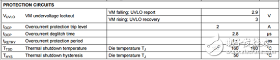
Figure 6: Protection circuit
Functional block diagram
This functional block diagram is a visual representation of the integrated circuit (Figure 7). It gives you a general idea of ​​the internal operation of the motor drive. You can refer to this block diagram to determine how the power tree is configured, how the output should be connected, and how the logic inputs/outputs are set.
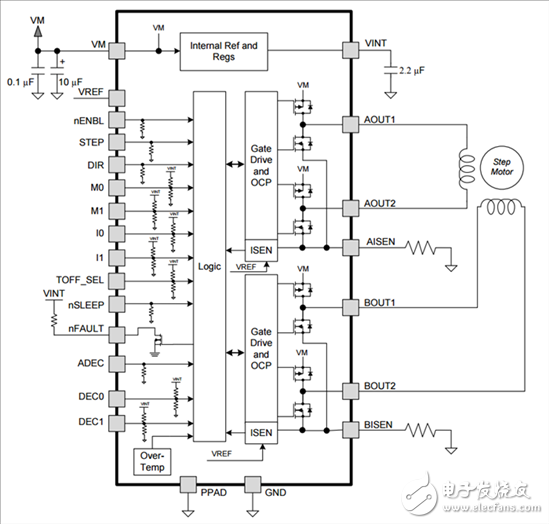
Figure 7: Functional Block Diagram
Layout example
Light Stand,Ring Light Stand,Photo Studio Light Stand,Mobile Phone Tripod Stand
SHAOXING COLORBEE PLASTIC CO.,LTD , https://www.colorbeephoto.com