Circuit characteristics
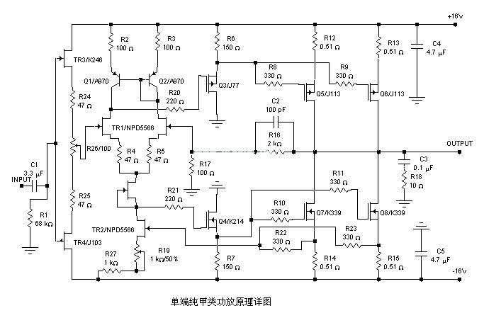
1. This power amplifier uses a current negative feedback circuit (most of Japan's famous golden throat power amplifiers use a current negative feedback circuit). The current negative feedback amplifier can well take into account the two indicators of nonlinear distortion and transient intermodulation distortion, and the conversion rate ratio The voltage negative feedback amplifier is better, and can provide the ideal amplification effect.
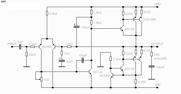
2. The power amplifier adopts a fully symmetrical circuit, a complementary push-pull amplification form, and the input stage uses a constant current source as a load, which effectively isolates the power supply noise and reduces nonlinear distortion, so that the power amplifier has extremely low noise, clean background, and analysis Strong.
3. The power amplifier circuit is simple, pure DC circuit, frequency bandwidth, small transient distortion, fast response, wide dynamic range, and DC servo circuit is adopted, and the output is automatically zeroed.
4. The high-frequency low-noise frequency dedicated name tube is used in the audio amplifier circuit of the power amplifier, and the signal-to-noise ratio and conversion rate of the power amplifier have been improved.
5. Two pairs of Toshiba high-power famous tubes are used as the class A parallel output for each channel of the final stage current amplification. The two tubes are connected in parallel, which improves the damping coefficient and enhances the driving ability of the circuit. It is very easy to drive large speakers with low impedance!
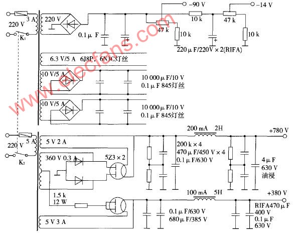
6. This power amplifier uses rectification and filtering (using two 10,000 uF / 50V Japanese famous brand electrolysis), speaker protection and left and right channel amplification circuits on a circuit board, and carefully sets the input and output ground wires, and the radiator is also It is fixed on the circuit board, and it is connected to the pre-stage volume control circuit and 400W dual 32V toroidal transformer when in use (if you do not need the pre-stage, you only need to add a volume potentiometer, you can choose the Japanese ALPS square blue shell Volume dedicated potentiometer, and use silver-plated shielded wire).
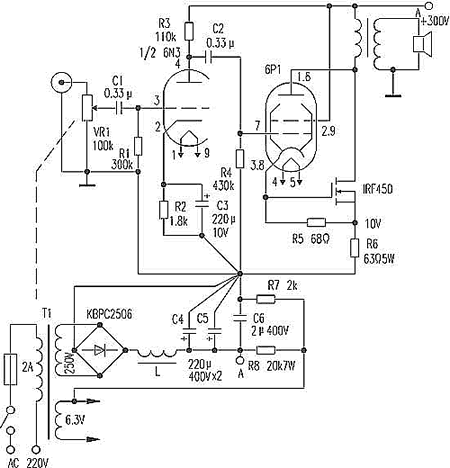
Component selection and debugging
1. The circuit board adopts epoxy glass fiber board, and all circuits are silver-plated.
2. The resistors are all metal film resistors (all-color five-ring low-noise high-precision resistors at small currents, ceramic resistors for the final power tube emitter resistors), and Japanese high-quality black diamonds, ELNA, and rubies.
3. The amplifier should emit beautiful sound. In addition to using excellent lines, high-quality components must also be selected, and the tubes at all levels are strictly matched. The input-level tubes use Japanese Toshiba A970 / C2240. The sound is warmer and softer. T5, T6 uses 2N5551 / 2N5401, voltage amplifying stage T7, T8 adopts Toshiba fever famous tube A1145 / C2705, push class adopts Hitachi medium power pair B649 / D669, the final power output tube requires Fr≥30MHz, Vceo≥160V, PCM≥150W , This power amplifier uses A1943 / C5200 from Toshiba of Japan (must be original, the original tube is of good character and long life, especially suitable for use in class A power amplifier), the constant voltage tube adopts Hitachi D669 and fixes it with the power tube On the same radiator. The tubes of all the above audio amplification channels should be strictly matched, and the β value of the two tubes should be less than 3%. As long as the matching is strict, the midpoint potential should be below tens of millivolts.
Under the conditions of installation and inspection, without connecting the sound source and the speaker, adjust VR1 to the maximum value, disconnect the power resistor of the power tube, turn on the power, pay attention to observe whether there are abnormal phenomena, such as component heating , Smoke, etc. If there is such a phenomenon, the power should be checked to find out that the problem has been solved and then the next step of debugging.
Connect back to the emitter resistance of the power tube, and then check the midpoint voltage if there is no problem. (If the transistors are strictly matched and the DC servo circuit is normal, the midpoint voltage should be below tens of millivolts.) Then test R25 / R26 / R27 / R28 voltage, slowly adjust VR1 so that the voltage across it is 110mV, at this time the quiescent current of the final stage is about 1000mA (ie 500mA per tube), then measure the midpoint potential unchanged, continue to energize 15- Measure again after 30 minutes, both channels are debugged above, everything is fine. This power amplifier has an output power of 120W per channel on an 8Ω load (about 60W in Class A).
You can listen to it after the machine is burned: the author uses Marantz CD as the sound source. The speakers use Hivi R1C + SS6N's self-made bookshelf monitor speakers. Rich sense of layering, high-frequency slenderness, roundness, beautiful and beautiful, especially when playing genuine Hugo CDs, the singer's tooth sounds and breathing sounds are clear and audible, fully reflecting the advantages of Class A amplifiers!
ME-308 pure DC current negative feedback type A power amplifier compared with TDA7294 current negative feedback power amplifier, ME-308 pure DC current negative feedback type A power amplifier has much better sound quality than TDA7294 current negative feedback power amplifier, and even If you listen to music for a long time, your ears will not feel harsh and upset, but the more you listen, the more you want to listen to the beautiful and beautiful music. Class A sake!).
Figure 2 is a scheme of a combined power amplifier consisting of ME-308 pure DC current negative feedback Class A amplifier and KA-307 Karaoke Class A pre-board or ME-128 Class A pre-board, etc. If you want to add virtual surround sound (QS7779 ), BBE sound effect enhancement processing circuit (BA3884, etc.) can be inserted in front of KA-307. The transformer uses 400W dual 32V + dual 12V toroidal transformer. When assembling, pay attention to the processing noise of the ground wire, and the sound quality and karaoke effect are very good! !

Follow WeChat

Download Audiophile APP

Follow the audiophile class
related suggestion
The principle of the field effect tube to control the working current is completely different from that of ordinary transistors, which is much simpler than ordinary transistors.

The five-pole power amplifier tube FD422 is used to make a single-ended Class A power amplifier. The design of this circuit is based on the principle of "simpleness first", which can reduce installation errors. Follow first ...

845 single-ended Class A amplifier circuit diagram will be 6N8P
What is a pure Class A amplifier The so-called Class A or pure Class A amplifier is actually two sub-classes of the power amplifier classified by static operating point. According to this division, ...
Field effect tube characteristics and the artistic charm and evaluation of the production of audio amplifiers with single-ended Class A amplifiers Audio amplifiers can be divided into electronic ...
Single-ended Class A power amplifier circuit Below, we introduce a single-ended pure ...
A 20W single-ended pure class A power amplifier circuit diagram, the circuit is very simple, used yuan ...
The power amplifier made with the voltage regulator set is a pioneering idea for electronics enthusiasts ...
![[Photo] NE5532 20W pure class A amplifier driven in parallel](http://i.bosscdn.com/blog/20/06/41/5131158379.jpg)
This is a Class A power amplifier with an output power of 18W. The final stage uses a current series negative feedback circuit (the bypass capacitors at both ends of the output stage self-sufficient bias resistor are cancelled) ...
Many audiophiles are happy to make power amplifiers, but most of them are limited to some single-chip sets such as LM1875, LM3886, LM4766, TD ...
'+ data.data.username +' '; dom + ='
The fast Ethernet POE Switch supports 60-watt PoE budget to power up to 4 IEEE 802.3af (or 2 IEEE 802.3 at) compliant powered devices simultaneously. The PoE features make fast Ethernet POE switch an efficient and cost-effective solution for SMB, SOHO or other similar fields where there is deployment of PoE network for the wireless access points, IP-based surveillance cameras or IP phones anywhere else.
To satisfy the increasing demand of PoE for Fast Ethernet (FE) networking, N-net has developed this series of PoE FE switch.
Fast Ethernet POE Switch,4 Ports Ethernet POE Switch,Small Fast Ethernet POE Switch,8 Ports Ethernet POE Switch,10/100M POE Switch, POE Switch 10/100M
Shenzhen N-net High-Tech Co.,Ltd , http://www.nnetswitch.com