Disadvantages of passive filters: Poor load carrying capacity, no amplification effect, unfavorable edge characteristics are not steep, and the levels affect each other.
RC filter1, the choice of C value: C can not be selected too small, otherwise the load capacitance has a great impact on the filter circuit, the input capacitance of the general IC often l ~ lOpF input capacitance. If the value of C is too large, the high-frequency characteristics of the filter circuit will be affected because the high-frequency characteristics of large capacitors are generally not good.
2, the choice of R value: R value is too small will increase the power supply load, R value is too large will consume more energy.
The biggest drawback of the RC filter circuit is that he not only consumes the signal energy we wish to suppress, but also consumes the signal energy we wish to retain. In addition, due to the limitation of the high-frequency characteristics of the capacitor, it cannot be used in a case where the frequency is too high. For example, an LC filter needs to be used for a number of MHz or more.
Capacitor filter circuitCapacitor filter circuit
When analyzing the working principle of the capacitor filter circuit, it mainly uses the blocking characteristics and energy storage characteristics of the capacitor. The pulsating DC voltage output from the front rectifying circuit can be decomposed into a DC voltage and a set of alternating currents with different frequencies. The AC voltage part flows from the capacitor to the ground. However, the DC voltage part cannot be blocked due to the blocking characteristics of the capacitor. Grounding flows to the next circuit. In this way, the capacitor removes the AC component of the original one-way ripple DC voltage.
In addition, the capacitor filter circuit can also be explained by the capacitor energy storage characteristics. When the one-way pulsating DC voltage is at the high peak, the capacitor is charged, and when it is at the low peak voltage, it is discharged, thus storing the high peak voltage to the low peak voltage. Release it again. The rugged unidirectional pulsating DC voltage is converted into a relatively smooth DC voltage.
The capacity of the filter capacitor is usually relatively large, and it is often the largest capacitor in the whole circuit. The filter capacitor has a large capacity and a good filtering effect. Capacitor filter circuit is the most commonly used one of various filter circuits.
How to select the power filter capacitor, and grasp its essence and method, it is not difficult.
1) Theoretically ideal capacitor's impedance decreases with increasing frequency (1/jwc), but due to the inductance effect of the pin at both ends of the capacitor, the capacitor should be seen as a LC series resonant circuit, and the self-resonant frequency The device SFR parameter, which means that when the frequency is greater than the SFR value, the capacitor becomes an inductor. If the capacitor is filtered to ground, when the frequency exceeds FSR, the suppression of interference is greatly reduced, so a smaller capacitor is needed in parallel to ground. Can you think about why? The reason is that the small capacitance, SFR value, provides a ground path for high-frequency signals, so we often understand this in the power supply filter circuit: large capacitors account for low frequencies, small capacitors account for high frequencies, the fundamental reason is SFR (self-resonance The value of frequency is different, but of course you can also think about why? If you think from this point of view, you can understand why the capacitance of the power filter is as close as possible to the ground.
2) Then in the actual design, we often have doubts. How do I know the SFR of the capacitor? Even if I know the SFR value, how do I choose the capacitance of different SFR values? Is a capacitor or two capacitors selected? The SFR value of the capacitor is related to the capacitor value and the pin inductance of the capacitor. Therefore, the 0402, 0603 of the same capacitance value or the SFR value of the in-line capacitor will not be the same. Of course, there are two ways to obtain the SFR value. ) Device Data sheet, such as 22pf0402 capacitor SFR value of about 2G, 2) directly measure the self-resonant frequency through a network analyzer, think about how to measure? After knowing the SFR value of the capacitor, use a software simulation, such as RFsim99, to select one or two circuits based on whether or not there is enough noise suppression ratio in the operating band of the circuit you are supplying. After the simulation, that is the actual circuit test, such as debugging mobile phone receiver sensitivity, LNA power supply filtering is the key, good power supply filter can often improve a few dB.
The essence of the capacitor is to communicate with AC and DC. In theory, the larger the power filter capacitor, the better. However, due to the leads and the PCB layout, the capacitor is actually a parallel circuit of the inductor and the capacitor (the resistance of the capacitor itself cannot be ignored sometimes). This introduces the concept of the resonant frequency: ω=1/(LC)1/ 2 Below the resonant frequency, the capacitor is capacitive, and the capacitor above the resonant frequency is inductive. As a result, large capacitors filter low-frequency waves and small capacitors filter high-frequency waves.
This can also explain why the capacitive filtering frequency of the same capacitance STM package is higher than the DIP package.
As for how much capacitance is used in the end, this is a reference:
Capacitor resonant frequency
Capacitance value DIP (MHz) SMT (MHz)
1.0μF 2.5 5
0.1μF 8 16
0.01μF 25 50
1000pF 80 160
100 pF 250 500
10 pF 800 1.6 (GHz)
But it is only a reference, in the words of the old engineer - mainly by experience. The more reliable method is to connect two capacitors, one large and one small, in parallel because of the high frequency characteristics of the large capacitors and the high frequency characteristics of the small capacitors. General requirements differ by more than two orders of magnitude to obtain a larger filter band.
2. Inductor filter circuit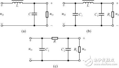
The principle of the inductor filter circuit is also similar to the capacitor filter, but also due to the inductor's direct blocking characteristics and energy storage characteristics. The explanation of energy storage is the same principle as the capacitor. When the filter circuit of the inductor is explained in terms of the direct blocking characteristic, the inductor blocks the part of the AC voltage that is decomposed by the unidirectional pulsating DC voltage. The capacitor is shorted to ground. The larger the inductance is, the better the filtering effect is, and the filter circuit is rarely used by the inductor alone, and it is generally used in combination with the capacitor.
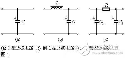
3. L-shaped RC filter circuit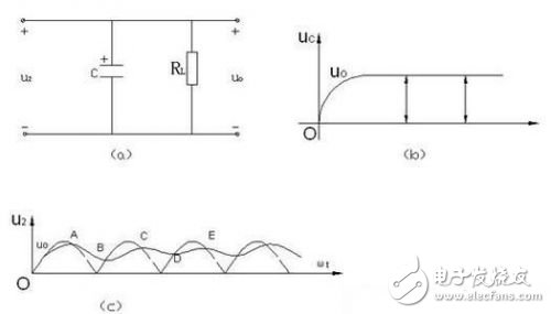
L-shaped RC filter circuit is to add a resistor in front of the capacitor in the ordinary capacitor filter circuit, the resistor is connected in series in the circuit, and the capacitor is connected in parallel in the circuit, then the resistor and the capacitor form an L-shape, so called They are L-shaped RC filter circuits. Its filtering principle and filtering effect are similar to those of the ordinary capacitor filtering circuit. At this time, the capacitor and the resistor also constitute a voltage divider circuit. Since the capacitive reactance of the capacitor is small, the partial pressure of the AC component is greatly attenuated, so that the AC The quantity is short-circuited to the ground through the capacitor, achieving the purpose of filtering. For the DC voltage part, because the capacitor is isolated from the DC, the capacitor does not divide the resistor and the DC does not flow through the capacitor. In such a filter circuit, if the resistance of the resistor does not change, increasing the capacity of the filter capacitor can increase the filtering effect, and the larger the capacity of the filter capacitor, the better. If the capacity of the filter capacitor is constant, increasing the resistance of the resistor can also increase the filtering effect, but the resistance of the filter resistor cannot be too large, because the resistance of the filter resistor is too large, the DC output voltage will become smaller.
The main reason for LC filtering is that the inductance of the inductor is small and the DC loss is small. The inductive reactance of the alternating current is large and the filtering effect is good. The disadvantages are bulky and bulky. high cost. Used in demanding power circuits.
The resistor in the RC filter consumes a part of the DC voltage, and R cannot be made large, and is used in a circuit where the current is less demanding. The RC is small in size and low in cost. The filtering effect is not as good as the LC circuit.
LC filter is generally used in high frequency circuit or power supply circuit while RC is used in low frequency circuit
The LC filter has a frequency range of 1 kHz to 1.5 GHz. Due to the Q value of the inductor, the frequency response is not steep enough.
1, RC filter is easier to miniaturize or integrate than LC filter, LC is relatively large in relative volume;
2, RC filter is depleted, LC filter can theoretically be no loss, so the power supply circuit is generally LC circuit;
3, RC is smaller than LC and the cost is at the end;
4, RC is used in low frequency circuit, LC filter is generally used in high frequency circuit;
5, RC filter resistance to consume part of the DC voltage, R can not be made very large, used in the circuit current is not high demand. RC small size, low cost. The filtering effect is not as good as the LC circuit; the LC filtering is mainly the inductance of the inductor is small, and the DC loss is small. The inductive reactance of the alternating current is large and the filtering effect is good. The disadvantages are bulky and bulky. high cost. Used in demanding power circuits.
6, the more the number of filtering stages is better, but brings higher losses and higher costs, so it is not recommended to exceed 3 levels;
7, RC filter is often used in combination with an operational amplifier to form an active filter, mostly as a filter for low-frequency signals. For example, use as a loop filter in a phase-locked loop
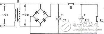
4. π-shaped RC filter circuitFirst of all, from the structural point of view, this filter circuit is composed of two capacitors and a resistor, which is actually a resistor in the L-shaped filter circuit before adding a capacitor ground to become a π-shaped RC filter circuit. The two capacitors perform filtering at the same time, and the latter filter capacitor can further filter the DC voltage not filtered in front of the capacitor, so that the two capacitors are filtered at the same time, and the filtering effect is certainly more ideal. The capacity of the first filter capacitor can be increased to improve the filtering effect, but the capacity of the first filter capacitor cannot be too large, because when the power is turned on and the first filter capacitor is too large, the charging time will be too long. This charging current flows through the rectifier diode. When the charging current is too large and the duration is too long, the rectifier diode will be damaged. Therefore, when this π-shaped RC filter circuit is adopted, the capacity of the first capacitor can be slightly reduced. By adjusting the L-shaped RC filter circuit behind to improve the filtering effect.
Î -shaped RC filter circuit
5. Multi-section π-shaped RC filter circuitThe multi-section π-shaped RC filter circuit is followed by an L-shaped RC filter circuit followed by an ordinary π-shape RC filter circuit to form a multi-section π-shape RC filter circuit. The filtering principle is the same as that of the ordinary π-shaped RC filter circuit above, except that this filter circuit has multiple DC voltage output terminals, and the more the DC voltage filtering effect of the subsequent output terminals is better. The first filter output has the highest voltage and the last filter output has the lowest voltage. This is mainly due to the voltage drop across the resistors. Multi-section π-shaped RC filter circuit is the most used filter circuit in the whole circuit.
6. π shape LC filter circuitπ shape LC filter circuit
This filter circuit is basically the same in structure as an ordinary π-shaped RC filter circuit except that the resistor is replaced with an inductor. Because resistors have the same resistance for both DC and AC, and the inductor has large resistance to AC inductance and small resistance to DC inductance, this can not only reduce the DC output voltage but also reduce the DC output voltage because the inductor does not exist for DC power. Inductive reactance does not have a voltage drop to DC like a resistor. The straight-through blocking characteristic of the inductor is the biggest advantage of this filter circuit, but the cost of the inductor is high so this filter circuit is not used much by the π-shaped RC filter circuit.
Wooden headphones are a type of headphones that is different from metal and plastic materials. Wooden headphone can let you enjoy the wonderful music. However, Wooden Wireless Headphone has strict standard of select materials. This is more related to personal preferences. If the density of wood is large, the dampen will be lower, it is easier to drive. If the density of wood is small, the ability to isolate noise is relatively weak. Therefore, we need to choose the earphone that suits us according to the sound prefer by our ears.

Wood Headphones,Wood Earphones,Wooden Headphones,Wooden Wireless Headphones
Shenzhen Linx Technology Co., Ltd. , https://www.linxheadphone.com