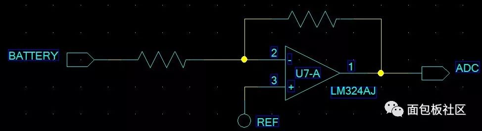
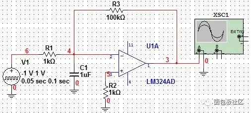
In 2004, I helped my friend to make a nickel-metal hydride charger. When the nickel-hydrogen battery was fully charged, there was a slight drop in voltage to identify whether it was full. For example, a 1.2V Ni-MH battery, when it is fully charged, the voltage is 1.35V. After a gradual decline, the voltage can be less than 1.30V. Therefore, the MCU needs to intermittently detect the voltage across the battery, and then charge it for about 3 seconds, then check the voltage across the battery. Because you need to identify the small voltage that drops, you need to add a level of op amp to amplify the magnitude of this drop, as shown below:
At that time, I just entered the society and had little practical experience. In order to improve the amplification performance and improve the stability, I took a small capacitor on the inverting input of the op amp. I remember it is about 10nF, as shown below:
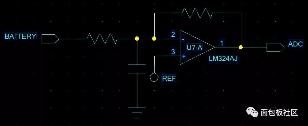
When debugging the program, it was found that the signal of the battery step-down was difficult to detect. It was often found that the battery was full of heat for a long time. This problem has been plagued for a period of time. The friend brought it back to Hong Kong and debugged it with a hardware person. When I looked at the signal, I finally found that there was a short-term oscillation in the output of the op amp, and this oscillation caused the signal sampling problem. So I quickly thought that I had added this capacitor and imagined the whole oscillation process in my mind. Analyze to a friend. This superfluous behavior eventually led to the failure of this project. In the past few years, I have done an infrared temperature tester with a temperature range of 400 to 1200 degrees. The PID infrared sensor is used, and the current-to-voltage amplification part of the circuit is as follows:
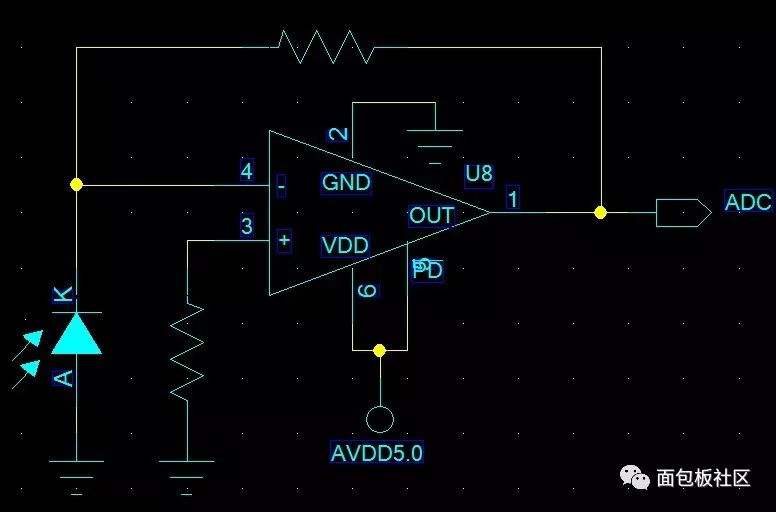
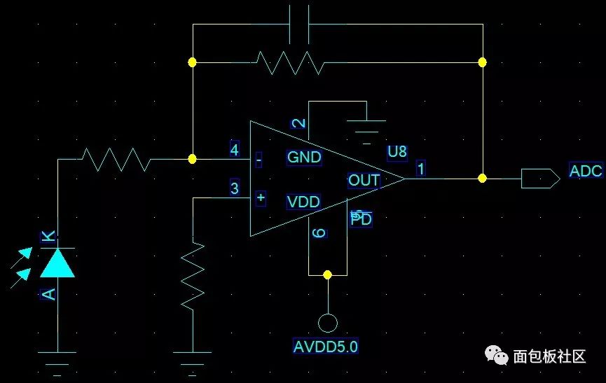
During the test, it was found that the temperature measurement was inaccurate near 700 degrees. Finally, the output was observed with an oscilloscope. It was found that at this temperature point, the output oscillated. This time I immediately thought that because of the PID sensor, the internal resistance is high, the parasitic capacitance is large, and equivalent. A capacitor is connected in parallel with the inverting input, similar to the amplification of the NiMH battery, so immediately improve the following circuit:
During the mobile phone test, the test found some inferior mobile phone chargers. The oscilloscope measured that the ripple of the output voltage, in addition to the switching ripple near 100KHz, there is a sine wave near 5K based on fluctuations around 5V, such as output voltage. 5V, in fact, it fluctuates at a frequency of 5KHz between 4.8 and 5.2V. How strange is this fluctuation? The above three cases are encountered by me. Although the first two problems have been solved, I still have confusion. With my deep understanding of the operational amplifiers, I realize that these problems are related to the phase, but I see a lot. The book on op amps tells us that a stable amplification requires a 180-degree negative feedback. If the phase is at 360 degrees, it may cause oscillation. This depends on the amplification factor. If the feedback signal is at 270 degrees? In fact, the problem caused by the phase is not too much. I have been doing technology for so many years, that is, I have encountered such a few cases, but I have seen a lot of information, such as the filtering of the PLL phase-locked loop, the feedback of the switching power supply, and some references of the operational amplifier. The circuit, which writes that phase compensation is needed, actually removes these compensations and seems to have no problems, so this keeps me wondering what is going on? This also makes everyone not very concerned about the phase problem. Last year, at the invitation of a friend, I recorded a video of the op amp. In order to record the video, I analyzed the phase in depth and finally understood what happened in the phase.
Most of our circuit applications are working in steady state, such as amplifying a signal, switching power supply input and output is relatively stable, etc. For steady-state signals, the phase problem is not prominent, even if the phase is 360 degrees, but as long as the system The loop magnification is less than 1, and it will not cause oscillation. In the era when the triode was just emerging, some amplifier circuits also work in the bootstrap state, typically the AM radio. However, in the case of a step change in the input and output signals, because each mutation causes the system loop to be unbalanced and the system needs to be balanced again, then this phase (the amplification gain is not discussed here) determines the time period into equilibrium, that is, With a phase of 180 degrees, the new balance can be entered as quickly as possible, while at 360 degrees, it takes a long time to enter another balance. You can understand 180 degrees as just damping, the more you deviate from 180 degrees, the longer the damping oscillation will take.
Here are the simulation results for multisim:
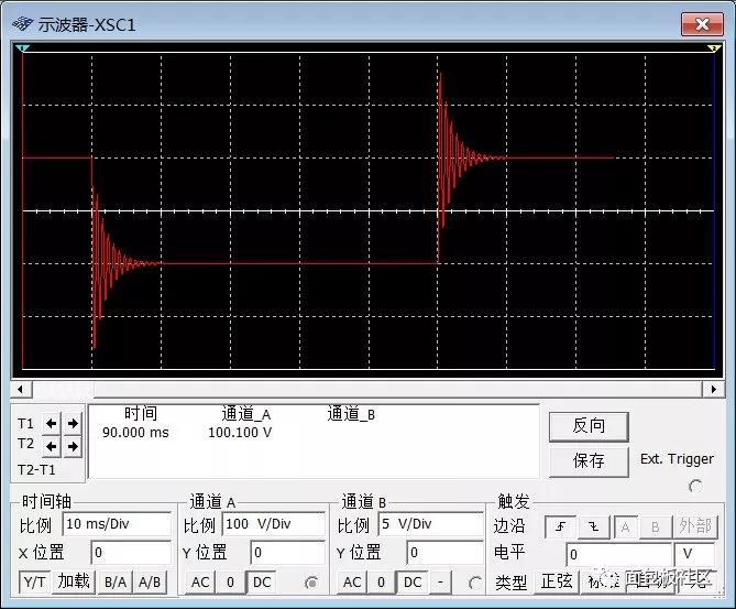
The effect of C1 is 1uF: the steady state is relatively fast:
C1 is 10uF, and the steady state time is longer:

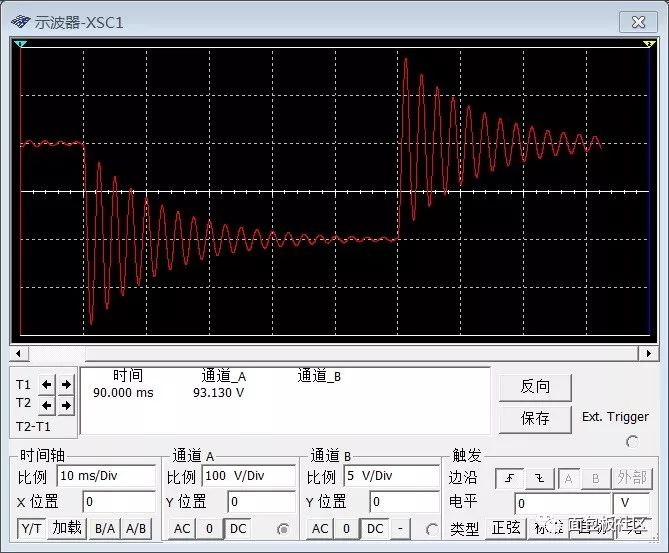
Therefore, in the feedback system with step mutation, we should make the circuit work at 180 degrees as much as possible to improve the speed of the system again.
Genki Ippai 1.0 uses high-tech temperature control, food grade pod and high-quality material device. We also upgrade to type-C interface for charging faster. We have developed various flavors for Genki Ippai Pod Systems. Up to 11 flavors provide consumers with more choices. What's more, you can use other brand`s vape pen with our vape pod.
We offer low price, high quality Disposable E-Cigarette Vape Pen,Electronic Cigarettes Empty Vape Pen, E-cigarette Cartridge,Disposable Vape,E-cigarette Accessories,Disposable Vape Pen,Disposable Pod device,Vape Pods to all over the world.
GenkiIppai Pods 1.0,Pod Systems Vape,Vape Pod Device,ZGAR GenkiIppai Pods 1.0 Pod System Vape Kit,Pod System Mini Vape Pod Device
Zgar International (M) SDN BHD , https://www.szdisposable-vape.com