Good grounding of the instrument is very important to the service life of the instrument and the safety of the operator. The original plan of this article was a two-day technology sharing. In order to let everyone better understand, we will put it on the same day.
Part1 Correctly understand the grounding of the instrument
I believe that many engineers may have encountered numb hands in the instrument shell during the use of the instrument. This can happen even when using laptops or other home appliances in ordinary times. Some people think that this is caused by leakage. In fact, the numb hand of the instrument shell is mainly caused by poor grounding of the instrument.
1 What damage can be caused by poor grounding?
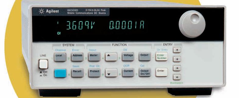
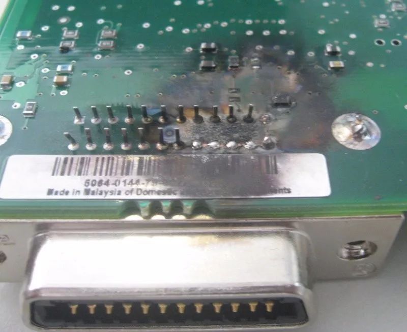
This is an example of instrument damage caused by poor grounding. This is a Keysight power supply. We opened the casing of the instrument and found that the GPIB interface of the instrument had been burned out. If you look closely, you can find that some pins have melted.
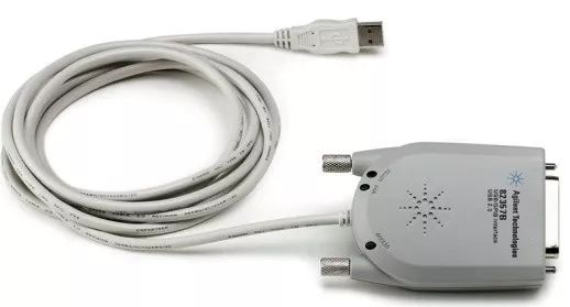
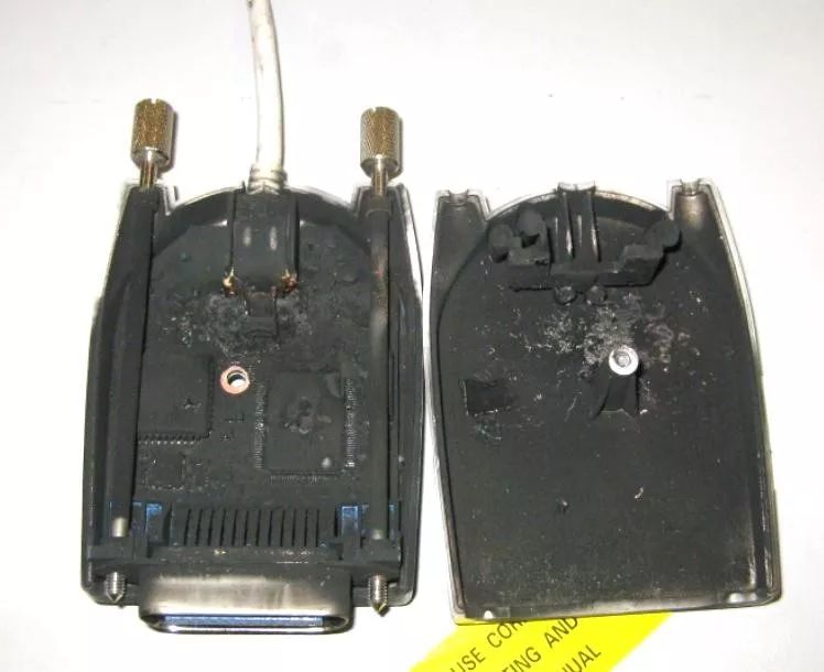
And what about the GPIB card connected to the instrument? After disassembling, it was found that the circuit board that was supposed to be green had been burned to black. Why does poor grounding have such a big impact on the instrument?
2 Causes of electrification of the instrument housing
The reason lies in the power filter. This device exists in most instruments and is used to filter out noise from the 220V mains.
Amplify the power frequency converter, we can see its circuit schematic. On the left is a 220V power line, the upper and lower ends are live and neutral wires, the voltage difference between them is 220V, and point E is the ground wire in the power line. The upper and lower ends on the right are also the live and neutral wires of the instrument, and the voltage between them is also 220V, and point E is the shell of our instrument.
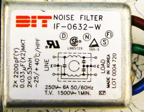
If the instrument case and the ground wire of the power cable are in good contact, the two filter capacitors in the picture can filter out the noise in the mains. But once the instrument case and the ground wire of the power cord are disconnected, and the capacitances of these two capacitors are equal, the two capacitors will become voltage dividing capacitors. The outer shell of the instrument also carries half of the 220V voltage, which is 110V AC voltage. At this time, if the operator touches the metal casing of the instrument, it will be hit by the 110V AC voltage.
Let's look at an example of instrument connection. The spectrum analyzer in the figure is normally grounded, but the signal source is not grounded. In this case, the housing of the signal source has an AC voltage of 110V. If you use an RF cable to connect the spectrum analyzer to the signal source, will the instrument be damaged?
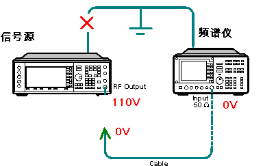
If it is connected normally, it will not. Because the 110V voltage of the signal source shell will be introduced into the shell of the spectrum analyzer through the outer ring of the N-type cable, and then into the ground wire of the power cord through the shell of the spectrum analyzer. But what we are worried about is that if there is no horizontal alignment when connecting the cable, the inner core of the N-type cable touches the outer shell of the signal source, and the 110V voltage will be introduced into the spectrum through the inner core of the cable. The analyzer and radio frequency components were removed, causing damage to many spare parts of the spectrum analyzer.
If the grounding is poor, the same fault will occur at all connection ports such as GPIB, serial port and USB port.
3 Reasons for poor grounding
With the advancement of our country's power grid construction, there are basically no problems with power supply quality and power grounding. What caused the poor grounding of the instrument? The biggest reason is actually the use of bad power strips.
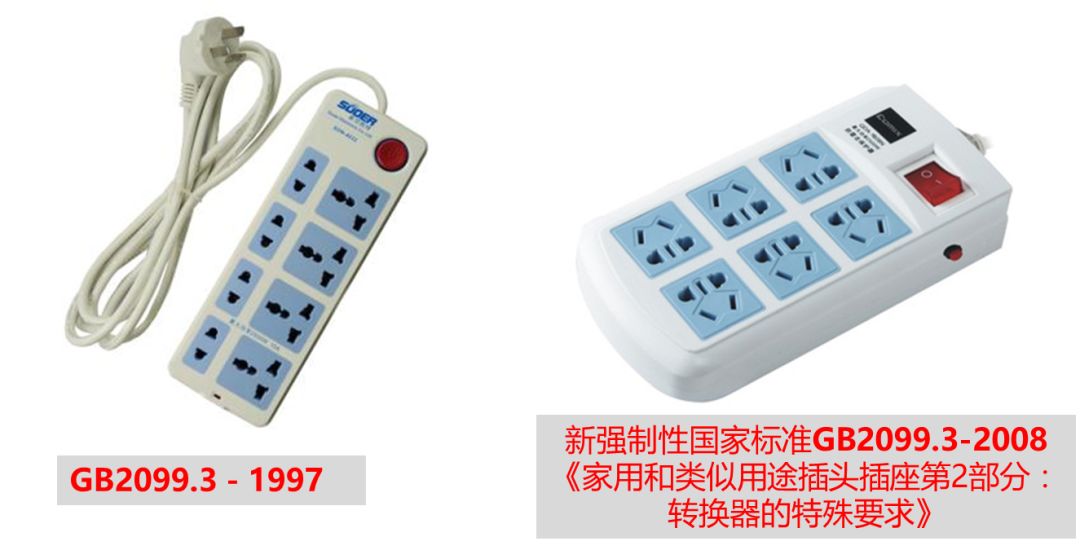
The picture on the left is the socket of the old national standard, also known as the universal socket; the picture on the right is the socket of the new national standard. The sockets of the old national standard are relatively large, mainly to facilitate the insertion of various standard plugs. After using for a period of time, the internal reed is easy to loosen, resulting in insufficient connection between the power cord and the power strip, resulting in poor grounding of the instrument.
The second reason is the use of poor quality power strips. We disassembled two different power strips. It is found that the good quality is made of 0.5mm phosphor bronze, which can be used more than 5000 times. Inferior power sockets use 0.4mm brass with cadmium plating. After a few times of use, the holding force becomes smaller. The power cords are also very different. The copper wire used for good quality power strips is very thick, while the copper wire used for poor quality power strips is very thin, which is easy to break and the instrument is not grounded.

The third cause of poor grounding is the power cord. We recommend using the national standard power cord in the middle of the figure below. Other American standards, British standards, and European standards are not recommended. The reason is that their grounding posts are thicker than the national standard power cords and they need to use universal power strips. After using these power cords, the internal reeds are easily loosened.
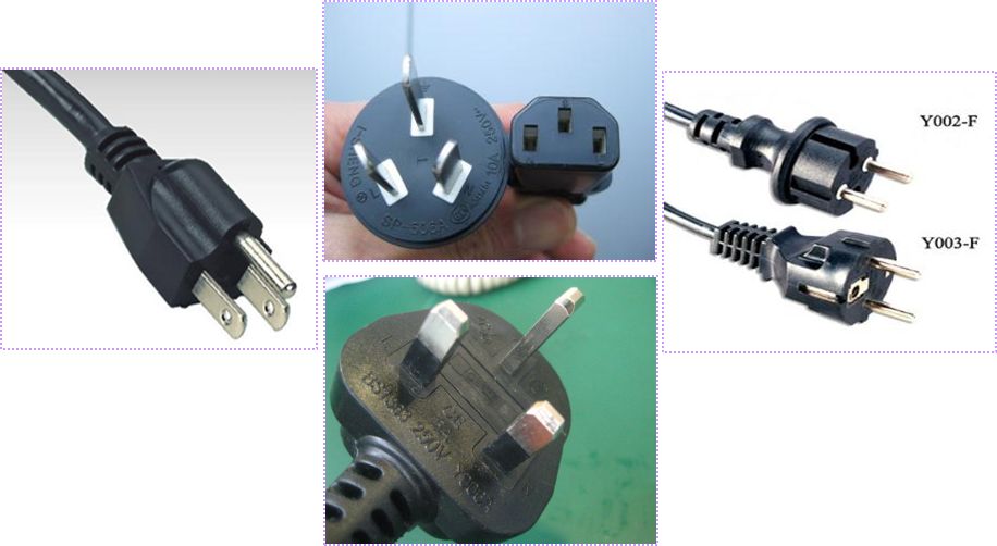
Therefore, as long as you pay a little attention to the power strip and power cord in the laboratory, you can effectively prevent poor grounding of the instrument and avoid damage to the instrument.
Part2 Three methods to judge the grounding of the instrument
Know the hazards caused by poor grounding of the instrument and how to avoid poor grounding of the instrument. Let us introduce three methods to judge whether the instrument is well grounded.
1 Use a socket tester
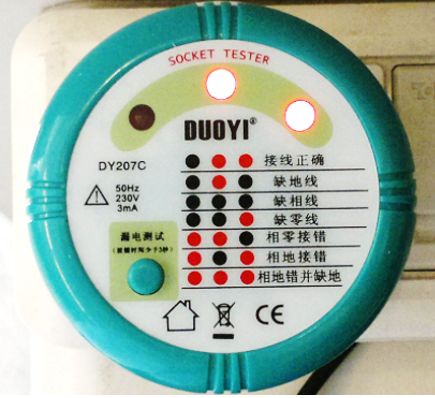
The picture shows the socket tester. After inserting these socket testers into the power strip, according to the corresponding indicator light, it can be judged whether the power wiring of the power strip is good. If there is a lack of ground wire, the tester will display that the middle light is on, and both sides are off.
It should be noted that: the green button at the bottom left of the tester is to test whether the leakage protection switch is working properly. Pressing it will cause the circuit protection switch to automatically trip. Before pressing this button, please turn off the instrument and other electrical appliances first.
2 use electric pen
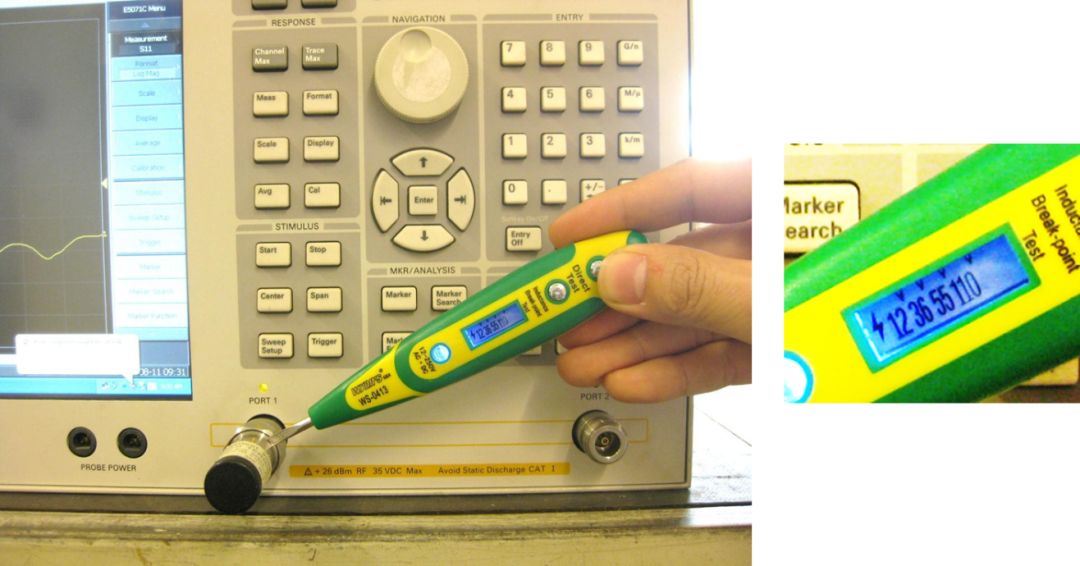
Perhaps the first thing many people think of when it comes to poor grounding is to use an electric pen. We can use the electric pen to directly test the metal part of the instrument shell. On the electric pen in the picture, the 110V indicator light is on, indicating that the instrument case has at least 110V AC. This instrument is not grounded and needs attention. If you touch the instrument shell at this time, you will get an electric shock.
3 use a multimeter
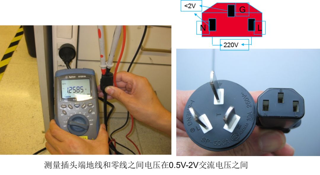
Adjust the multimeter to the AC voltage range and connect the ground wire and neutral wire of the power cord of the instrument. We recommend that the voltage difference between the ground wire and the neutral wire be between 0.5V and 2V.
It should be noted that if the direct voltage difference between the ground wire and the neutral wire is 0, it is possible that the electrician has connected the ground wire and the neutral wire together and sent it to the neutral terminal of the distribution box. At this time, there is no ground wire, which is very dangerous. Therefore, we recommend that the voltage difference between the ground wire and the neutral wire be between 0.5V and 2V.
The above are three simple methods to judge the grounding status of the laboratory. In the case of good grounding, the instrument can avoid unnecessary damage.
Shenzhen Jiesai Electric Co.,Ltd , https://www.gootuenergy.com