This article first introduces the differences between the instrumentation amplifier and the operational amplifier. Secondly, it introduces the working principle, characteristics and application of the instrumentation amplifier. Finally, it introduces the operational principle and basic circuit of the operational amplifier.
What is the difference between an instrumentation amplifier and an operational amplifier?The instrumentation amplifier is a closed-loop gain unit with a differential input and a single-ended output at the opposite reference. In most cases, the two inputs of the instrumentation amplifier are impedance balanced and have high resistance values, typically ≥109 Ω. Its input bias current should also be low, typically 1 nA to 50 nA. As with operational amplifiers, their output impedance is very low, typically only a few milliohms (mΩ) at low frequencies. The closed-loop gain of the op amp is determined by the external resistor connected between its inverting input and its output. Unlike amplifiers, instrumentation amplifiers use an internal feedback resistor network that is isolated from its signal input. An input signal is applied to the two differential inputs of the instrumentation amplifier, the gain of which can be preset either internally or by the user via pins connected to an internal or external gain resistor. The gain resistor is also isolated from the signal input.
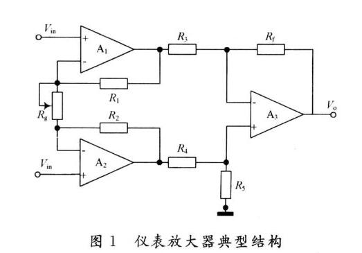
Dedicated instrumentation amplifiers are usually expensive, so we would like to use an ordinary op amp to form an instrumentation amplifier. The answer is yes. Using three general op amps can form an instrumentation amplifier. The circuit is shown below:
The output voltage expression is shown in the figure.
See here everyone may ask how the above expression is derived? Why can the above circuit implement an instrumentation amplifier? We will discuss these issues below. Before this, we first look at the following differential circuits that we are familiar with:
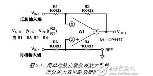
If R1 = R3 and R2 = R4, then VOUT = (VIN2_VIN1)(R2/R1)
This circuit provides an instrumentation amplifier function that amplifies differential signals while rejecting common-mode signals, but it also has some drawbacks. First, the non-inverting and inverting inputs have relatively low impedance and are not equal. In this example, the VIN1 inverting input impedance is equal to 100 kΩ, and the non-inverting input impedance of VIN2 is equal to twice the inverting input impedance, which is 200 kΩ. Therefore, when a voltage is applied to one input terminal and the other terminal is grounded, the differential current will flow in accordance with the applied voltage received by the input terminal. (This source impedance imbalance reduces the CMRR of the circuit.)
In addition, this circuit requires that the ratio of resistors R1 / R2 and R3 / R4 match very precisely, otherwise, the gain of each input will have a difference, which directly affects the common-mode rejection. For example, when the gain is equal to 1, all resistors must be equal. If there is a 0.1% mismatch in one of these resistors, the CMR drops to 66 dB (2000:1). Similarly, if the source impedance has an imbalance of 100 Ω, it will drop the CMR by 6 dB.
To solve the above problem, we add voltage followers to the positive and negative input terminals of the op amp to increase the input impedance. As shown below:
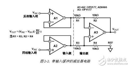
The two preamplifiers above are used as voltage followers. We have now changed to noninverting amplifiers. The circuit is as follows:
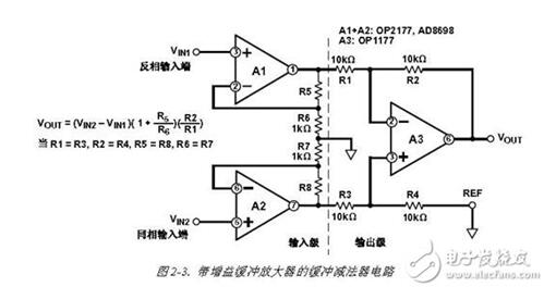
The output voltage expression is as shown above. When the circuit shown in the figure above increases gain (A1 and A2), it adds the same gain to the differential signal and also adds the same gain to the common-mode signal. That is, the above circuit does not increase in the common mode rejection ratio with respect to the original circuit.
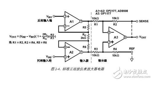
Below, we must start the most clever changes! Look at the circuit first:
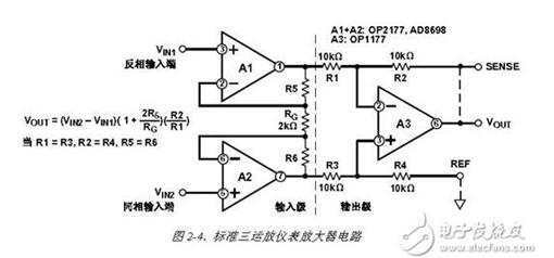
This standard three-op-amp instrumentation amplifier circuit is a clever improvement to the circuit with a buffered subtractor. Like the previous circuit, the A1 and A2 op amps above buffer the input voltage. However, in this configuration, a single gain resistor RG is connected between the summing points of the two input buffers instead of R6 and R7 with a buffer subtractor circuit. Since the voltage at each amplifier's summing point is equal to the voltage applied to its respective positive input, the entire differential input voltage is now present across RG. Since the differential voltage of the input voltage after amplification (at the outputs of A1 and A2) is present across the three resistors R5, RG, and R6, the differential gain can be adjusted by changing only RG.
This connection has another advantage: once the gain of this subtractor circuit is set with a ratio-matched resistor, there is no longer any need for resistor matching when changing the gain. If R5 = R6, R1 = R3 and R2 = R4, then VOUT = (VIN2-VIN1)(1+2R5/RG)(R2/R1) Since the voltage across RG is equal to VIN, the current through RG is equal to VIN/ RG, so the input signal will gain through A1 and A2 and be amplified. However, it should be noted that the common-mode voltage applied to the input of the amplifier has the same potential across the RG so that no current is generated on the RG. Since no current flows through RG (and no current flows through R5 and R6), amplifiers A1 and A2 will operate as unity gain followers. Therefore, the common-mode signal will pass through the input buffer with unity gain, and the differential voltage will be amplified by the gain coefficient of [1+(2RF/RG)]. This means that the common-mode rejection ratio of the circuit is increased by [1+(2 RF/RG)] times that of the original differential circuit!
Theoretically, the user can obtain the required front-end gain (determined by the RG) without increasing the common-mode gain and error. That is, the differential signal will increase proportionally with the gain, while the common-mode error will not, so the ratio [gain (differential input voltage)/(common-mode error voltage) will increase. Therefore, CMR theoretically increases directly in proportion to gain, which is a very useful feature.
Finally, due to structural symmetry, the common-mode errors of the input amplifiers, if they are tracked, will be eliminated by the output stage subtractors. This includes errors such as common-mode rejection with frequency transformation. These characteristics are the explanations for the wide application of this three-op-amp architecture.
Here, we have derived the classic circuit; the ins and outs: differential amplifier - "pre-voltage follower -" voltage follower becomes a non-inverting amplifier - "a three-op amp instrumentation amplifier.
Instrumentation Amplifier IntroductionInstrumentation Amplifier Operation
It takes a lot of time and effort to build instrumentation amplifiers (IAs) with discrete components, and the use of integrated instrumentation amplifiers (IAs) or differential amplifiers is a simple and feasible alternative. In order to better understand the instrumentation amplifier (IA) and to understand the importance of the Common Mode Rejection Ratio (CMR), this is illustrated with a Wheatstone bridge transmitter. R1 = R2 = R3 = R4 = 5kΩ, excitation voltage (Vex ) is 10V. In this way, under no-load conditions, the calculation of "bridge" can be obtained:
V1=Vex(R2/(R2+R1)), V1=5VV2=Vex(R3/(R3+R4)), V2=5V So: V=V1-V2=5V-5V=0V Transmitter output is two outputs of bridge The voltage difference at the end (ΔV). Assume that there is a certain excitation on the 4 active arms of the bridge, and make the values ​​of R1 and R4 increase, and the values ​​of R2 and R3 decrease. At this time, if: R1=R4=5001Ω, R2= R3 = 4999Ω, Vex = 10V, then available: V1 = 5.001V  V2 = 4.999V, in fact, people are concerned about the signal:
ΔV=V1-V2=2mV. Therefore, the calculation of the common mode voltage (CMV) shows that even if the bridge is unbalanced, the common mode voltage (CMV) is still equal to (V1+V2,/2=5V. Ideally, the output of this circuit is: Vo=ΔV· Gain.
The above calculations show that it is difficult to measure a weak voltage signal when there is a large common-mode signal, and ΔV (in mV) can be obtained by measuring two large voltage signals V2 and V1. Voltage can be in volts.
Instrumentation Amplifier Features and Applications
Instrumentation amplifiers are specialized precision differential voltage amplifiers that are derived from operational amplifiers and are superior to operational amplifiers. The instrumentation amplifier integrates key components inside the amplifier. Its unique structure makes it highly common mode rejection ratio, high input impedance, low noise, low linearity error, low offset drift gain setting flexibility, and ease of use, making it in the data Acquisition, sensor signal amplification, high-speed signal conditioning, medical instruments, and high-end audio equipment are all highly favored.
Operational Amplifier IntroductionHow Operational Amplifiers Work
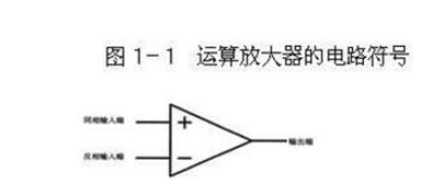
The op amp has two inputs and one output, as shown in Figure 3-1, where the input labeled "+" is the "inverting input" and not the positive terminal), and the other is labeled "one. The “inverting input†of the “number†input can also not be called negative. If the same signal is input from the two input terminals in succession, the output signal with the same voltage but opposite polarity will be obtained at the output: The output signal is in-phase with the in-phase input signal and inverted with the inverting input signal.
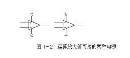
The power supply connected to the operational amplifier can be single-power or dual-power, as shown in Figure 3-1. Operational amplifiers have some very interesting features. Flexible use of these features can lead to many unique uses. In general, these features can be combined into two:
1. The operational amplifier's magnification is infinite.
2. The input resistance of the operational amplifier is infinite and the output resistance is zero.
Now let's briefly look at what conclusions can be drawn from the above two features.
First, the gain of the op amp is infinite, so as long as the input voltage at its input is not zero, the output voltage at the output will be as high as the positive or negative supply. The output voltage should have been infinitely high, but Power supply voltage limit. Specifically, if the input voltage at the non-inverting input is higher than the input voltage at the inverting input, even if it is only a very high point, the output of the operational amplifier will output a voltage that is the same as the positive supply voltage; The input voltage of the phase input is higher than the input voltage of the in-phase input, and the output of the operational amplifier will output a voltage equal to the negative supply voltage (if the operational amplifier uses a single power supply, the output voltage is zero).
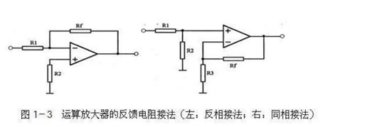
Second, because the amplification factor is infinite, the op amp cannot be used directly as an amplifier. The output signal must be fed back to the inverting input (called negative feedback) to reduce its amplification. As shown in the left picture in Figure 1-3, the function of R1 is to return the output signal to the inverting input of the op amp. Since the voltage at the inverting input is opposite to the output voltage, the circuit's amplification is reduced. , is a negative feedback circuit, resistor Rf is also called negative feedback resistor.
Also, because the input of the op amp is infinite, the input of the op amp has no current input—it only accepts voltage. Similarly, if we imagine an infinite resistance between the non-inverting input and the inverting input of the op amp, the voltage across the resistor will not be able to form a current, and there will be no current. According to Ohm's law, both ends of the resistor There will be no voltage, so we can also think that the two input voltages of the operational amplifier are the same (the voltage in this case is a bit like using a wire to short the two inputs, so we call this phenomenon again "virtual short").
Operational amplifier basic circuit
A single-supply op amp requires an external virtual ground. Typically, this voltage is VCC/2. The circuit in Figure 2 can be used to generate a VCC/2 voltage, but it will reduce the system's low-frequency characteristics.
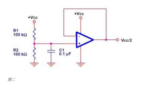
R1 and R2 are equivalent and are selected by the allowable power dissipation and allowable noise. Capacitor C1 is a low-pass filter to reduce the noise from the power supply. Buffered op amps can be ignored in some applications.
Three Phase Portable EV Charger
Three Phase Portable Ev Charger,Ev Home Charger,Portable Electric Charger,Electric Charger
Yangzhou JERI New Energy Co., Ltd. , https://www.jrevcharging.com