Causes of starting surge current
Figure 1 shows a simplified circuit of a typical electronics power supply section. C1 is a filter capacitor in parallel with the load. At the moment of power-on, the capacitor voltage cannot be abruptly changed, thus generating a large charging current. According to the first-order linear non-homogeneous equation established by the first-order circuit zero-state response model, the current value obtained by short-circuiting the filter capacitor can be obtained. This current is what we often call the input surge current. It is generated when the filter capacitor is initially charged. The size depends on the amplitude of the input voltage when the power is turned on and the bridge rectifier and electrolytic capacitor. The total resistance of the loop.
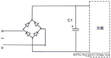
Figure 1 power supply schematic
Assume that the input voltage V1 is 220Vac, the internal resistance of the whole grid (including rectifier bridge and filter capacitor) Rs=1Ω. If the power input waveform is turned on when the input waveform reaches 90 degrees, the peak value of the surge current will reach I=220. ×1.414/1=311(A). Although this surge current is very short, if it is not suppressed, it will shorten the life of the input capacitor and rectifier bridge, and may also cause the input power supply voltage to decrease, so that other power equipment using the same input power supply will be powered down instantaneously. The normal operation of the device causes interference.
Inrush current suppression
There are many ways to suppress the inrush current. Generally, the resistor current limiting method is adopted in the medium and small power supply to suppress the startup surge current. Figure 2 is a schematic diagram of a common 110V/220V dual input power supply. As an example, we analyze how to suppress the inrush current using an NTC thermistor.
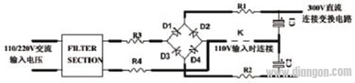
Figure 2 Schematic diagram of 110/220Vac dual input power supply
The NTC thermistor, a negative temperature coefficient thermistor, is characterized by a non-linear drop in resistance with increasing temperature. NTC is generally divided into a temperature measuring thermistor and a power type thermistor. The NTC thermistor used to suppress surge refers to a power type thermistor.
In Figure 2, R1~R4 are the locations where the thermistor surge suppressor is normally placed. For dual voltage input products that are compatible with both 110Vac and 220Vac inputs, two NTC thermistors should be placed simultaneously in the R1 and R2 positions so that the inrush current can be disconnected when the 110Vac input cable is connected and the 220Vac input cable is disconnected. Consistently, an NTC thermistor can be placed separately at R3 or R4. For single-voltage products with only 220Vac input, simply place one NTC thermistor at the R3 or R1 position.
Its working principle is as follows:
At normal temperature, the NTC thermistor has a high resistance value (usually 5Ω or 10Ω), which is the nominal zero power resistance value. Referring to the example of Figure 1, when the 10Ω NTC is connected in series, the starting surge current is: I=220×1.414/(1+10)= 28(A), which is 10 times lower than the 311A ​​when the NTC thermistor is not used. It acts to suppress the inrush current.
After the power is turned on, due to the rapid heating and temperature rise of the NTC thermistor, its resistance value will rapidly drop to a small level in the millisecond period, generally only a few tens of ohms to several ohms, compared to the conventional fixed In the case of resistance current limiting resistors, this means that the power dissipation in the resistor is reduced by several tens to hundreds of times due to the drop in resistance, so this design is very suitable for products with high conversion efficiency and energy saving, such as Switching power supply.
After the power is turned off, the NTC thermistor will gradually return to the nominal zero power resistance value with its own cooling, and the recovery time will take several tens of seconds to several minutes. The next time you start, cycle through the above process.
Improved power supply design
The above-described circuit using the NTC surge suppressor has an energy-saving characteristic as compared with a circuit using a fixed resistor. For some special products, such as industrial products, sometimes customers will ask the following requirements: 1. How to reduce the failure rate of NTC to improve its service life? 2. How to minimize the power consumption of NTC? 3. How to make the power circuit connected to the NTC thermistor adapt to the application conditions of the cycle switch?
For the first and second points, because the main function of the NTC thermistor is to suppress the surge, the energy consumed by the product after normal startup is not needed. If there is a feasible way to make the NTC thermistor from normal. This requirement can be met by cutting off the working circuit.
For point 3, first analyze why products using NTC thermistors cannot be switched frequently. From the analysis of the working principle of the circuit, we can see that under normal working conditions, there is a certain current through the NTC thermistor. This working current is enough to make the surface temperature of the NTC reach 100 °C ~ 200 °C. When the product is turned off, the NTC thermistor must be fully restored from the high temperature and low resistance state to the normal temperature and high resistance state to achieve the same surge suppression effect as the previous one. This recovery time is related to the dissipation factor and heat capacity of the NTC thermistor, and the cooling time constant is generally used as a reference in engineering. The cooling time constant refers to the time (in seconds) required for the NTC thermistor to cool to 63.2% of its temperature rise after heating from a predetermined medium. The cooling time constant is not the time required for the NTC thermistor to return to normal, but the larger the cooling time constant, the longer the recovery time required, and vice versa.
Under the guidance of the above ideas, the improved circuit of Figure 3 is produced. At the moment of power-on of the product, the NTC thermistor suppresses the inrush current to a suitable level, and then the product is powered normally. At this time, the relay coil is energized from the load circuit, and the NTC thermistor is cut off from the working circuit. . In this way, the NTC thermistor only works when the product is started, and does not access the circuit when the product is working properly. This not only extends the service life of the NTC thermistor, but also ensures that it has sufficient cooling time and can be used in applications requiring frequent switching.
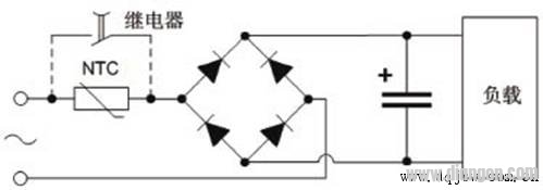
Figure 3 Schematic diagram of power supply design with relay bypass circuit
Selection of NTC thermistor
The following points should be considered in the selection of NTC thermistors:
Maximum rated voltage and filter capacitor value
The size of the filter capacitor determines how large the NTC should be used. For a NTC thermistor of a certain size, the size of the filter capacitor that is allowed to be connected is strictly required. This value is also related to the maximum rated voltage. In power applications, the power-on surge is due to capacitive charging, so the ability of the NTC thermistor to withstand inrush current is typically evaluated with the allowable capacitance at a given voltage value. For a specific NTC thermistor, the maximum energy that can be withstood has been determined. According to the energy consumption formula E=1/2×CV2 of the resistance in the first-order circuit, the allowed access capacitance can be seen. The value is inversely proportional to the square of the rated voltage. Simply put, the larger the input voltage, the smaller the maximum capacitance value allowed to be accessed, and vice versa.
The specification of NTC thermistor products generally defines the maximum capacitance value that is allowed to be accessed at 220Vac. Assume that the maximum rated voltage of an application condition is 420Vac and the filter capacitance value is 200μF. According to the above energy formula, the equivalent capacitance value at 220Vac can be calculated as 200×4202/2202=729μF, so 220Vac must be selected during the selection. Allows access to models with capacitance values ​​greater than 729μF.
Maximum allowable starting current value for the product and operating current for long-term loading on the NTC thermistor
The maximum allowable starting current value of the electronic product determines the resistance of the NTC thermistor. Assuming that the power supply rated input is 220Vac, the internal resistance is 1Ω, and the maximum allowable starting current is 60A, then the minimum resistance of the selected NTC in the initial state is Rmin=(220×1.414/60)-1=4.2(Ω). At this point, there are generally one or more NTC thermistors that meet the conditions. In this case, select the following method.
When the product is working normally, the current applied to the NTC thermistor for a long time should not exceed the current specified in the specification. According to this principle, a suitable resistance value can be selected from a plurality of resistors having a resistance greater than 4.2 Ω. Of course this refers to the situation at room temperature. If the ambient temperature of the work is not normal temperature, the derating design of the NTC thermistor is required according to the principles mentioned below.
NTC thermistor working environment
Since NTC thermistors are greatly affected by the ambient temperature, generally only the resistance value at room temperature (25 ° C) is given in the product specification. If the application conditions of the product are not at normal temperature, or due to the design or structure of the product itself, When the ambient temperature around the NTC thermistor is not normal temperature, the resistance of the NTC in the initial state must be calculated before the above steps can be selected.
When the ambient temperature is too high or too low, the derating design must be based on the power reduction curve provided by the manufacturer. The power consumption curve generally has two forms, as shown in Figure 4.
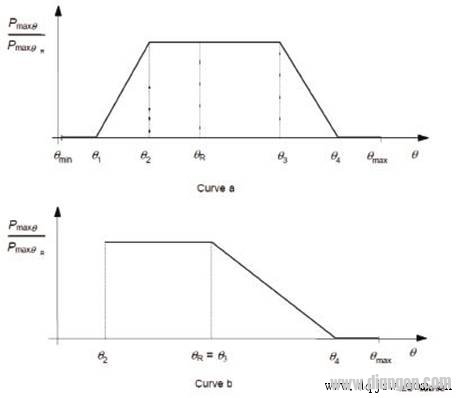
Figure 4 power reduction curve
For curve a, the maximum allowable continuous operating current can be expressed by the following formula:

For curve b, the maximum allowable continuous operating current can be expressed by the following formula:
In fact, many manufacturers have defined the ambient temperature category for their products. In practical applications, the ambient temperature at which the NTC thermistor should work should not exceed the upper/lower limit temperatures specified by the manufacturer. At the same time, care should be taken not to operate in a humid environment, as excessively humid environments can accelerate the aging of NTC thermistors.
in conclusion
It can be seen from the above analysis that the NTC thermistor type surge suppressor is used in the power supply design, and its ability to suppress the inrush current is equivalent to that of the ordinary resistor, and the power consumption on the resistor can be reduced by several tens to hundreds of times. For applications that require frequent switching, a relay bypass circuit must be added to the circuit to ensure that the NTC thermistor is fully cooled back to its original state. In product selection, the product series should be selected according to the maximum rated voltage and filter capacitor value. The resistance of the NTC thermistor should be selected according to the maximum starting current value allowed by the product and the operating current applied to the NTC thermistor for a long time. At the same time, it is necessary to consider the temperature of the working environment and appropriately derate the design.
A dramatically more leakproof system.
A cartridge so durable, every droplet has nowhere to go.
With a huge leap in battery life with 1000mAh, enjoy a 2-day vape.
New mesh coil, tight and smooth MTL.
All for an enduring vape.
Prevent overheating accidents by pressing the button five times.
After the LED flashes in white, blue, and green in a row, Wenax H1 is
safe to go.
Enjoy three different output levels by simply pressing the firing
button three times.
The LED will indicate the status of the battery and the output
level. All operations are within one button.
geekvape wenax series box,geekvape wenax series replacement pods,geekvape wenax series mods,geekvape wenax series kit,geekvape wenax series pod kit
Ningbo Autrends International Trade Co.,Ltd. , https://www.mosvapor.com