Under the background of global energy shortage and increasing environmental protection requirements, all countries in the world have vigorously developed green energy-saving lighting. As a revolutionary energy-saving lighting technology, LED lighting is developing rapidly. However, the requirements for LED drive power are also increasing. High efficiency, high power factor, safe isolation, EMI compliance, high current control accuracy, high reliability, small size, low cost, etc. are becoming key evaluation indicators for LED drive power.
In the current LED power driver, electrolytic capacitors must be used, and small electrolytic capacitors can only last for several thousand hours. However, the use of the patented IC driver does not require the use of electrolytic capacitors, the life span of more than 40,000 hours, 10 times that of the original led driver, and the size of the patented IC driver is small, only a quarter of the original area, can be easily placed Into the LED bulb, you do not have to change the shape of the original bulb, so that the design is more simple, and more acceptable to users.
The higher the efficiency of the LED driving power supply, the better the LED's high luminous efficiency and energy saving. At the same time, the high switching operating frequency and high efficiency make the entire LED driving power supply easy to install in compact LED lamps. High constant current accuracy guarantees brightness and color consistency when using LED lighting in large quantities.
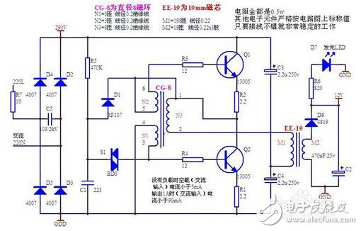
LED driver power circuit diagram is the same as other electrical power supply circuit. For example, using switching power supply circuit can make the load get good quality DC power supply, but the circuit diagram is not convenient to make. Here are two simple circuits for LED driver. In the power circuit diagram, there are few components in the LED driver power supply circuit, which is convenient to manufacture, and the component parameters are in the circuit for reference. The first, LED driver power circuit diagram is as follows:
The other, based on the AP1661 + AP3102 LED driver circuit schematic, as shown below:
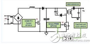
In the above figure, the second LED driver power supply circuit diagram: the circuit adopts Boost PFC+Flyback two-stage topology structure, and the control chip adopts PFC control chip AP1661, PWM control chip AP3102 and secondary side constant current control chip AP4310. The advantages of the LED driving power circuit diagram scheme are small input/output capacitance, small output ripple, isolated output, high power factor, current precision control within 2%, and high reliability.
Shenzhen Niimoo Innovative Technology Co., Ltd , https://www.niimootech.com