This paper designs the lighting control system for smart home applications through the combination of remote control technology and single-chip microcomputer. The system is based on the control system of single-chip microcomputer, and controls the system lighting by remote control. The solution mainly solves the signal transmission and reception, processes the different signals after the signal is processed and received, and realizes the switch and brightness adjustment of the light bulb through software programming.
introduction
Smart home refers to the use of advanced computer technology, network communication technology, and integrated wiring technology to organically combine various subsystems related to home life, and make home life more comfortable, safe and effective through overall management.
With the improvement of people's living standards and the development of electronic technology, home intelligence has begun to enter our daily life. People have been dissatisfied with the push-button manual switch to control the luminaire, thus developing a remote control system with a higher level of intelligent lighting control, which has low cost, high quality and flexible application. Due to its small size, low power consumption, strong function and low cost, infrared remote control is currently the most widely used communication and remote control method.
1 Basic principle of infrared remote control
Infrared remote control uses infrared (also known as infrared light) to transmit control signals to achieve remote control of the control object. Specifically, the transmitter emits an infrared command signal, which is received by the receiver and processed and identified by the receiver, and then passed through the corresponding control chip, and finally realizes various functions of the control object according to different signals received. Distance control.
The infrared emitter consists of a command button, a signal generating circuit, a frequency modulating circuit, a driving circuit, and an infrared emitting device, as shown in FIG. When the command key is pressed, the command signal generating circuit generates the required control command signal.
The control command signals here are distinguished by some different features. Commonly used distinguishing command signals are characterized by frequency characteristics and code group characteristics, that is, different instructions are represented by different frequencies or different coded telecommunication codes. These different command signals are frequency modulated, and finally the drive circuit drives the infrared emitting device to emit an infrared remote command signal.
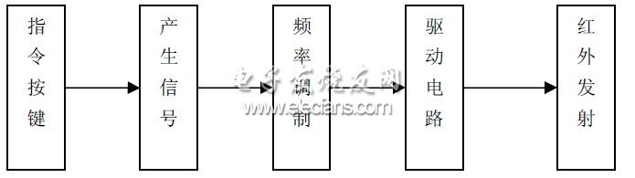
Figure 1 Composition of infrared emission
The infrared receiver is composed of an infrared receiving device, a preamplifier circuit, a signal demodulating circuit, and an instruction detecting circuit, as shown in FIG. 2 . When the infrared receiving device receives the infrared command signal of the transmitter, it converts the infrared light signal into an electrical signal and sends it to the preamplifier for amplification, and then demodulates by the demodulator, and the command signal detection circuit detects the command signal. Out, to achieve a variety of operations.
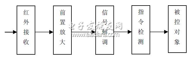
Figure 2 The composition of the infrared receiver
To implement the remote control function of the system, you must first select the way the signal command is transmitted. These control signal characteristics can be combined and encoded in various combinations depending on the manner of the remote control and the user's situation. Such as the combination of voltage polarity, the combination of electrical signal phase, the combination of electrical signal amplitude, the combination of frequency, the combination of pulse width, phase, amplitude and other parameters and pulse coding combination. The pulse coding combination method has the advantages of large command capacity, strong anti-interference ability, good confidentiality and easy implementation by logic circuit, and has been widely used.
2 system hardware circuit design
The infrared remote control circuit is composed of a transmitting circuit and a receiving circuit, and the transmitting part is composed of a button switching circuit, a control chip and an infrared transmitting circuit. When the remote control button is pressed, the microcontroller generates a corresponding control signal and transmits it through the infrared emitting diode. The receiving part is composed of an infrared receiving head, a control chip and a dimming circuit. When the infrared receiver receives the control pulse, it is processed by the single chip microcomputer to determine whether the light is dimmed or switched, and the corresponding operation is performed as needed, and the receiving system adopts It is powered by a single 5 volt supply voltage. As shown below:
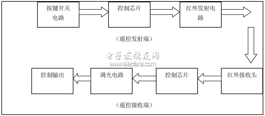
Figure 3 system design block diagram
2.1 Remote control system master chip
In this system, the 51 series AT89C51 chip is selected. The AT89C51 is a low voltage, high performance CMOS 8 bit with 4k byte Flash Programmable and Erasable Read Only Memory. Microprocessor, commonly known as microcontroller. The device is fabricated using ATMEL high-density non-volatile memory fabrication technology and is compatible with the industry-standard MCS-51 instruction set and output pins. Combining a versatile 8-bit CPU and flash memory in a single chip, ATMEL's AT89C51 is a highly efficient microcontroller that provides a flexible and cost-effective solution for many embedded control systems. The AT89C51 is a low-power, high-performance microcontroller with 40 pins and 32 external bidirectional input/output (I/O) ports. It also contains 2 external interrupt ports, 2 16-bit programmable timing counters, and 2 full The duplex serial communication port, AT89C51 can be programmed according to the conventional method, or can be programmed online.
It combines a common microprocessor and Flash memory, especially the flash memory that can be repeatedly erased and written to reduce development costs.
2.2 Infrared transmitting circuit module
In the design of the system, how the signal sent by the single chip is recognized by the infrared transmitting tube, and whether the transmitting tube can normally emit the infrared signal is a key problem to be solved by the transmitting circuit.
To emit an infrared signal, an infrared emitting device must be available. Infrared light-emitting diode (LED) is a kind of light-emitting diode that can generate infrared light. At present, the widely used infrared light-emitting diode emits infrared light with a wavelength of about 940 nm. The shape is the same as that of an ordinary light-emitting diode, but the color is different. Common infrared emitting diodes have black and transparent colors. The biggest difference between them and ordinary light-emitting diodes is that the emitted light is invisible light, while ordinary light-emitting diodes emit visible light of various colors [5]. Generally, infrared light-emitting diodes are divided into There are two types of structure: one is a remote-controlled emission type infrared light-emitting diode (the infrared-emitting diode used in the most commonly used hand-held remote controller); the other is a close-range emission type infrared light-emitting diode, which emits infrared light and Receive a common set. Since this design implements a home remote control, the first one can be used.
As shown in Figure 4, the system remote control transmission schematic diagram, P1.0 port is the key input port; P2.0 port is the infrared transmission port for outputting 38kHz carrier code, the pulse is amplified by 9013 (NPN) and then output by the infrared transmitting tube The 9th pin is the reset pin of the MCU, and the RC manual reset circuit is used; the 18 and 19 pins are connected to the crystal oscillator.
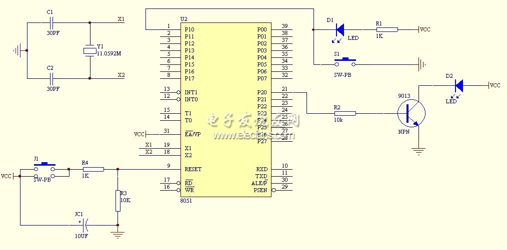
Figure 4 infrared emission circuit diagram
Chinese Tier 1 brand Solar Panel (Longi, Jinko, Trina, Canadian, Ja etc.)
This type of product is mainly Tier 1 solar module product in China, include Longi solar panel. Jinko solar panel, Canadian Solar panel, ja solar panel etc.all of which are among the top 10 world-renowned brands. The original A grade product is mainly mono crystalline and half cut cell solar modules, with a power range of 400watts to a maximum of 700watts.quality warranty is 25 years.
A grade, this type of film is characterized by a neat and uniform appearance, printed electrode grid lines, no broken grid, no surface stains, no leakage, no aluminum package, no hidden cracks, no scratches, no black core, no reverse current, stable electrical performance, and high conversion efficiency
Using solar cell testing equipment to measure and screen, the conversion efficiency, filling factor, and appearance that meet certain standards are first level. Generally, the conversion efficiency, filling factor, and appearance of first level are better than those of level B
The level of solar panels can be divided into first level, second level, third level, and fourth level, and the first level components can be divided into first level+and first level - two levels. The second level is also the same, and the cost difference between different levels of solar panels is also very large.
Chinese tier 1 brand solar panel
TIER 1 brand include
Longi, Jinko, Trina, JA, Canadian, znshine, etc.
quality warranty
25 years
grade
original A grade (each solar panel can be checked on official website with barcode)
power range
400watt to max 700watt

Tier 1 Solar Panel,Mono Solar Panel N Type,Solar Panels Bifacial 555 Watt,Solar Panel Mono Topcon Cell
PLIER(Suzhou) Photovoltaic Technology Co., Ltd. , https://www.pliersolarpanel.com