Today's switching regulators and power supplies are designed to be more compact and more powerful, but one of the challenges is that the ever-accelerating switching frequency makes PCB design more difficult. PCB layout is becoming a watershed to distinguish between a switching power supply design. This article will provide advice on how to achieve good PCB layout the first time.
Take a 3A switching regulator that reduces 24V to 3.3V as an example. At first glance, a 10W regulator won't be too difficult, so designers often can't help but go straight into the construction phase.
However, after adopting design software such as National's Webench, we can observe what problems the concept actually encounters. After entering the above requirements, Webench will select the company's 'SimplerSwitcher' series of LM25576 (a 42V input component including 3AFET). It is available in a TSSOP-20 package with a thermal pad.
Webench options include design optimizations for volume or efficiency, all of which are single options. That is, high efficiency requires a low switching frequency (reducing switching losses in the FET). Therefore, a large capacity of inductance and capacitance is required, and thus a larger PCB space is required.
Note: The maximum efficiency is 84%, and this maximum efficiency is achieved when the drop-to-input voltage is very low. In this case, the input/output ratio is greater than 7. In general, the two-stage lowers the stage-level ratio, but the efficiency obtained by the two regulators is not better.
Next, we choose the highest switching frequency for the smallest PCB area. High switching frequencies are most likely to cause problems in layout. The Webench then generates a circuit diagram containing all the active and passive components.
Circuit design
Referring to the current path of Figure 1, the path through which the FET flows in the on state is marked in red; the circuit in the off state of the FET is marked in green. We observed two different cases: two color regions and one color only region. We must pay special attention to the latter case because the current alternates between zero and full-scale voltage. These are all high di/dt regions.
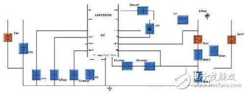
figure 1
High di/dt AC produces a large amount of magnetic field around the PCB conductor that is the primary source of interference for other components in the circuit, even other circuits on the same or adjacent PCB. Since the common current path is not AC, it is not a critical path and the effect of di/dt is much smaller. On the other hand, these areas are loaded more with time. In this example, the common path is from the diode cathode to the output and from the output ground to the diode anode. When the output capacitor is charged and discharged, the capacitor has an extremely high di/dt. All lines connecting the output capacitors must meet two conditions: they are wide due to large currents; they must be as short as possible to minimize di/dt effects.
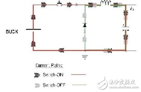
figure 2
In fact, designers should not adopt the so-called traditional layout method of routing wires from Vout and ground to capacitors. These wires should flow through large alternating current. It is better to connect the output and ground directly to the capacitor terminals. Therefore, the alternating current is only exhibited on the capacitor. The other wires connecting the capacitors are now flowing through almost constant current, and any problems associated with di/dt have been resolved.
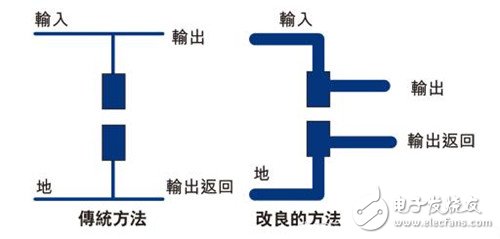
image 3
Grounding design is another common misunderstanding. Simply placing a ground plane at 'level2' and connecting all ground connections to it will not give good results.
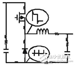
Figure 4
Power: 220V-240V 50/60Hz 1200W, Motor : Dual driving
1.Stepless speed control with pulse function2.Two driving connector for different attachments
3.Rotary chrome switch
4.Transparent splash-proof cover
5.5.8L stainless steel bowl(SUS 304)
6.Non slip feet
7.Power cord hiding box
8.Dishwasher safe attachments
9.Unique dough hook & mixer whisk are included.
10.Low noise, environment friendly
11.Cord length: 1.2m


Electric Hand Mixer,Fruit Mixer,Egg Mixer,Cake Beater
Housoen Electric Manufacture Co., Ltd. , https://www.housoenappliances.com