In the modern war mode, missile directional blasting can greatly improve the killing energy acting on the target direction, so that the missile can obtain greater hit and damage probability and combat capability. Fuze as an important component of missiles, with azimuth recognition capability is a prerequisite for missile directional blasting. As the core component of the fuze, the signal processing system is the main implementation unit of the azimuth recognition function and the target detection function. Its structure and performance have a critical impact on the overall performance of the fuze. With the development of FPGA and DSP technology, the application of digital signal processing technology in fuze greatly enhances the processing capability of fuze signals, which is beneficial to the realization of azimuth recognition fuze. Based on the FPGA+DSP architecture, this paper implements a fuze signal processor with 8-quadrant azimuth recognition capability.
1 Principle of identifiable position fuze system
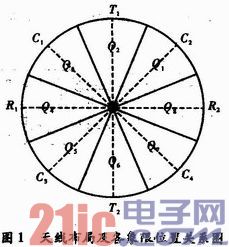
The azimuth recognition algorithm is designed to realize the azimuth recognition of the eight quadrants in the circumferential direction of the fuze. A total of four antennas are separated by dual-transmission and dual-transmission, and a 360° uniform detection field is formed in the circumferential direction of the missile. The layout is shown in Figure 1. T1/T2 is the transmitting antenna, and R1/R2 is the receiving antenna. According to the azimuth recognition algorithm, the azimuth recognition of 8 quadrants in Q1~Q8 can be realized.

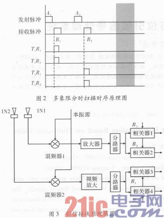
It is the ultimate goal of multi-quadrant time-division scanning to obtain four channels of Doppler signals according to the principle of time division multiplexing. The multi-quadrant time-division scanning in the algorithm uses the receiving branch to receive the echo at the same time, and then uses the received pulse correlation characteristic to separate the received echoes. This directional detection system is relatively simple to implement, has high transmission and reception isolation, and can be reduced back. The distance lobes of the Doppler. Figure 2 is a schematic diagram of multi-quadrant time-sharing scanning timing, and Figure 3 is a block diagram of the implementation of the fuze system.

2 signal processing system design
2.1 Functional requirements
The signal processor of the directional detection fuze in the design is a complex processor, which is implemented by digital frequency domain processing, including A/D conversion circuit and signal processing module, to realize sampling, quantization and digital signal of Doppler signal. FFT, CFAR processing, complete the detection of the target, start determination, interference discrimination. Its functions include: (1) Digitizing the 4-channel Doppler signal. (2) Time-frequency conversion and related frequency domain processing are implemented according to the 4-way Doppler signal. (3) A target presence signal is given when the target detection criterion is met. (4) Using the frequency domain peak of the Doppler signal as the target energy information, the four-way target energy information is compared to realize the azimuth recognition of the eight quadrants in the fuze circumferential direction.
2.2 How does the digital signal processing system work?
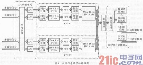
The target or ambient echo passes through the fuze receiving front end, and four Doppler echoes are obtained according to the time-sharing scanning principle, and four signals are simultaneously input into the signal processing circuit. The 4-channel Doppler signal is first sampled by A/D to form echo time domain data, and then FFT frequency domain analysis and coordinate system conversion, modulo operation based on linear approximation approximation algorithm, data transmission under multi-processor cooperative work The buffer is finally input into the DSP chip for target detection and orientation recognition. If a certain signal-to-noise ratio is satisfied, the target presence signal is given, and the target orientation recognition is continued under the premise of the target existence, and the target orientation information is output. The design signal processing system adopts FPGA+DSP frame plum, and the FPGA completes 4 FFT operations. The DSP completes the target detection and off-target azimuth recognition. Two FPGA chips and a single DSP chip make a multiprocessor work together. Digital signal processor. Figure 4 shows the block diagram of the fuse signal processing unit in this design.

2.3 FPGA unit design
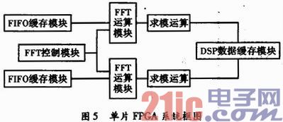
The two FPGA chips in the fuze signal processing system mainly realize the time-frequency domain conversion of the 4-channel Doppler signal and the pre-processing of the frequency domain information, and require four parallel processing. The FPGA chip selects two EP1K100QI208-2 of Altera Corporation, which are respectively recorded as FPGA1 and FPGA2, and the single-chip FPGA performs two-way FFT operation, modulo operation and cache of calculation results. The modular idea can greatly optimize the design of the digital signal processing system, enhance the readability and maintainability of the code, and adopt the modular design idea widely in the design to reasonably divide the functions in the signal processing. The monolithic FPGA mainly includes a FIFO buffer module, an FFT time-frequency conversion module, a modulo operation module, and a DSP data cache module. Figure 5 is a block diagram of the internal system of a single FPGA.

2.4 DSP unit design
In the design of the fuze signal processing system, TI's F2802 chip was selected as the main processor for the subsequent processing detection and discrimination of FFT operation. The F2812 has built-in flash memory and eliminates the need for an external memory chip. The F2812 is a high-speed mature DSP processor with strong digital signal processing capability. The maximum core frequency is up to 150 MHz. The system clock is set to 100 MHz in the program, which can meet the real-time requirements of signal processing. The stability of the device operation is guaranteed.
After receiving the interrupt request sent by the FPGA, the DSP signal processor reads the 128-point spectrum x(k) from the FPGA dual-port RAM, and selects the x(k) point by point to find the spectrum position of the target. The other line energy in the cell is added and averaged as the noise energy N. To weaken the spectrum leakage caused by signal truncation, when calculating the noise energy, remove the two adjacent spectral lines on both sides of the maximum spectral line, compare the ratio of the maximum spectral line and the noise energy with the established threshold, and determine whether the target exists, if not If there is, the next frame operation is performed; if it exists, the azimuth recognition program is entered to perform the azimuth recognition. If the target azimuth can be identified, the binary 3-bit azimuth indication signals 3b000 to 3b111 are given, respectively corresponding to the eight directions of the missile circumferential direction. . The DSP software processing flow chart is shown in Figure 6. 

Cummins Tube Brace,Cummins Oil Supply Tube,Cummins Wiring Harness,fuel supply pipeline Cummins
Chongqing LDJM Engine Parts Center , https://www.ckcummins.com