Device function
This article refers to the address: http://
In the MAX7461, the video signal is first sync-clamped to establish a DC level (see Figure 1). This eliminates low frequency noise, such as buzzing at 50Hz or 60Hz. It also avoids DC bounce when multiple sources switch to input.
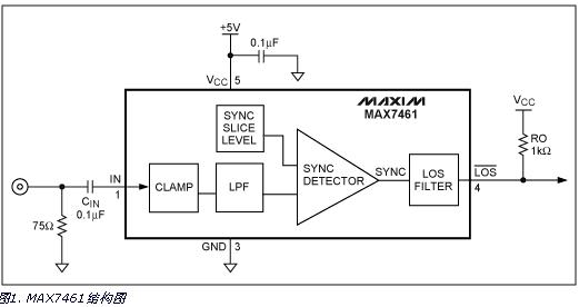
After clamping, the signal is low-pass filtered to eliminate the burst and chrominance signals, thereby avoiding false simultaneous detection and improving noise immunity. Subsequently, the device performs clipping processing on the clamped and filtered video signal, and extracts the synchronization signal by comparing the synchronous slice levels.
The resulting synchronization sequence passes through a LOS filter that enables the device to reliably and quickly detect the synchronization signal. The LOS filter measures the width and synchronization frequency of the sync signal.
Device performance
The MAX7461 not only detects if a sync signal is present, but also validates the signal. It does this by measuring the width and frequency of the signal, as shown in Figure 2.
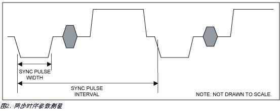
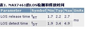
The typical value of the sync pulse width is 4.7 μs, the typical value of the NTSC sync pulse interval is 63.55 μs, and the PAL is 64 μs. The sync pulse width is distributed between 4.19 μs and 5.76 μs, considering that more color standards are used. In individual cases, the sync pulse interval even reaches 63.492 μs. Therefore, the device sets a sync pulse width and sync pulse interval window. For the determination of the valid sync signal, the device must detect several sync signals within the probe window (typically 2.2 ms). Once a valid sync signal is detected, the device must lose 3.4ms (typical) before indicating loss of synchronization. The detection and release time tolerances are shown in Table 1 below.
These algorithms, including measuring the sync width, the spacing of multiple sync signals, and hysteresis, enable very reliable, extremely high noise immunity for simultaneous detection.
Synchronous width and spacing windows can be set internally for reliable detection of all SDTV sync modes. If the input is an HDTV sync signal, the device will indicate a loss of synchronization. This is very important in a multi-standard environment where it is possible that the HD signal is incorrectly connected to the SD input.
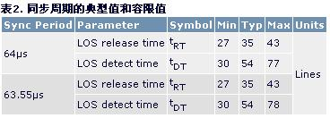
Therefore, when the MAX7461 detects a valid sync signal, it must detect the sync signal within the sync width and interval window (at least 2.2ms). After the probe, the valid sync signal must be lost at least 3.4ms, which is equivalent to 53 lines. Typical values ​​and tolerance values ​​are shown in Table 2.
Application and advantage
This section covers typical CCTV, automotive entertainment, and consumer applications. The processor of this type of system mainly completes the basic functions of the system. Although the synchronization signal loss detection is very important, it is attributed to the auxiliary function.
The system processor can perform the synchronization loss detection function. However, it must be monitored in real time, which typically consumes a lot of processing resources. Therefore, implementing the loss of synchronization function in a simple device can alleviate the real-time processing tasks of the system processor.
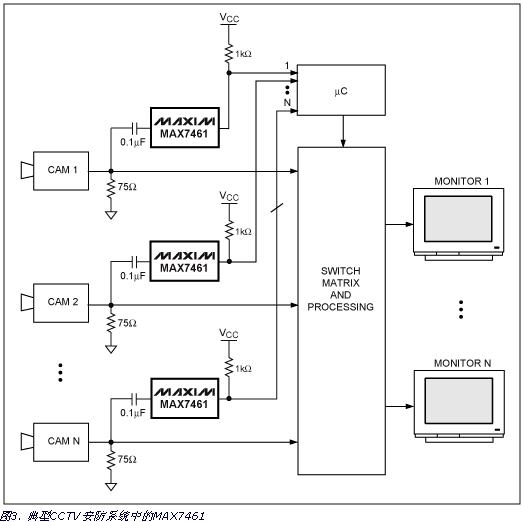
CCTV security system
In a typical CCTV security system (shown in Figure 3), it is critical that the system processor knows if a video source is working. In the monitoring environment of multiple cameras, most systems can only monitor and record some of the cameras connected to the system. Some systems are set up. If one camera is destroyed, another camera in the same location will immediately start monitoring and record. Therefore, it is important to implement fast switching between video sources.
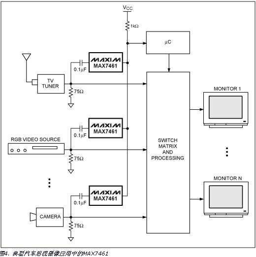
Rear view camera in automotive electronics
Automotive systems are becoming more and more complex. For example, some cars have adopted rear-view cameras to help drivers observe the environment behind the car and facilitate reverse. In this application (see Figure 4), especially when the visibility is poor at night, the video signal of the rear view camera should be continuously monitored. If the signal is wrong, the system can respond quickly. Using the MAX7461 instead of a system processor to do this can quickly detect signal failures.
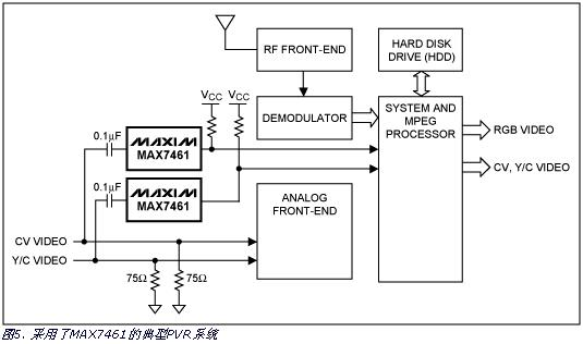
Personal camera (PVR) system
A typical PVR system is capable of not only recording internal decoder information, but also recording auxiliary analog inputs. The PVR system uses a complex system processor for cumbersome video signal processing. Therefore, the biggest benefit of using an external sync loss detector is to reduce the load on the processor. A typical application circuit for the MAX7461 in a PVR is shown in Figure 5.
in conclusion
This application note details the application of the MAX7461 for simultaneous loss of signal detection in a variety of systems. The MAX7461 is simple to use and provides an easy way to reduce system processor load.
The Connection Modules is one of parts of connection systems. Including 8/10 pair connection/disconnection krone module, switching, high band modules, quick connect module, 25pair splicing module, 10pair STG module, MDF, STB module.

LSA Module, Lighting Protector, Mounting Frame, STB Module, High Band Modules, STG Module Switch Module, Earth Module, Back Mount Frame
NINGBO YULIANG TELECOM MUNICATIONS EQUIPMENT CO.,LTD. , https://www.yltelecom.com