
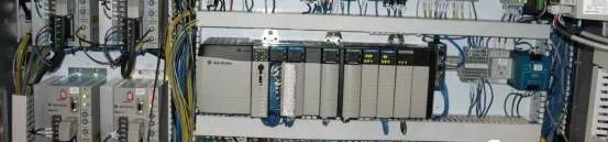
In recent years, with the development of society, PLC programmable controllers have been widely used in industrial production. At the same time, the requirements for its use by technicians are increasing year by year, so the requirements for the normal and stable operation of the system are getting higher and higher. The reliability of the PLC product itself can be guaranteed, but some incorrect operations in the application will cause a certain impact. Today, the editor compiled some tips in daily PLC applications for everyone, hoping to help everyone in daily use of PLC.
Grounding problem

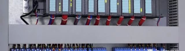
The PLC system grounding requirements are relatively strict, it is best to have an independent dedicated grounding system, but also pay attention to the reliable grounding of other equipment related to the PLC. When multiple circuit grounding points are connected together, unexpected current will be generated, resulting in logic errors or circuit damage. The reason for the different ground potentials is usually because the grounding points are separated too far in the physical area. When the devices that are far apart are connected by communication cables or sensors, the current between the cable and the ground will be Flowing through the entire circuit, even in a short distance, the load current of large equipment can change between it and the ground potential, or directly generate unpredictable currents through electromagnetic effects. Between power sources at incorrect grounding points, a destructive current may be generated in the circuit, which may damage the equipment. The PLC system generally chooses one point grounding method. In order to improve the ability to resist common mode interference, shielding floating technology can be used for analog signals, that is, the shielding layer of the signal cable is grounded at one point, the signal loop is floating, and the insulation resistance with the earth should not be less than 50MΩ
Anti-interference processing
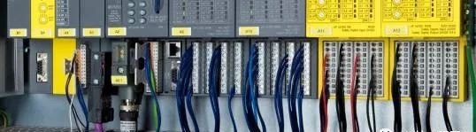
The environment of the industrial site is relatively harsh, and there are many high and low frequency interferences. These interferences are generally introduced into the PLC through cables connected to field devices. In addition to grounding measures, some anti-interference measures should be taken in the design and selection of cables and installation work:
1. The analog signal is a small signal, which is easily affected by external interference. Double-layer shielded cables should be used;
2. High-speed pulse signals (such as pulse sensors, counting code discs, etc.) should use shielded cables to prevent external interference and prevent high-speed pulse signals from interfering with low-level signals;
3. The frequency of the communication cable between PLCs is relatively high. Generally, the cable provided by the manufacturer should be used. If the requirements are not high, a shielded twisted pair cable can be used;
4. Analog signal lines and DC signal lines cannot be routed in the same slot as AC signal lines;
5. The shielded cables introduced and drawn in the control cabinet must be grounded, and should not be directly connected to the equipment through the wiring terminal;
6. The AC signal, DC signal and analog signal cannot share the same cable, and the power cable should be laid separately from the signal cable.
During on-site maintenance, the methods to solve the interference are: use shielded cables for the interfered lines and re-lay them; add anti-interference filtering codes to the program.
Eliminate line capacitance to avoid malfunction
There is a capacitance between the wires of the cable, and a qualified cable can limit this capacitance within a certain range. Even if it is a qualified cable, when the cable length exceeds a certain length, the capacitance between the lines will exceed the required value. When this cable is used for PLC input, the capacitance between the lines may cause the PLC to malfunction. , There will be many incomprehensible phenomena. These phenomena are mainly manifested as: the connection is correct, but the PLC has no input; the input that the PLC should have does not have, and the input that should not have is there, that is, the PLC inputs interfere with each other. In order to solve this problem, we should: 1. Use cables with twisted cable cores; 2. Shorten the length of the cables used as much as possible; 3. Separate the input cables that interfere with each other; 4. Use shielded cables.
Selection of output module

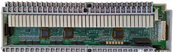
Output modules are divided into transistors, triacs, and contact types.
Transistor type has the fastest switching speed (generally 0.2ms), but the smallest load capacity, about 0.2~0.3A, 24VDC, suitable for fast switching, signal connection equipment, generally connected to frequency conversion, DC devices and other signals, should pay attention to transistor leakage The effect of current on the load.
The advantage of the SCR type is that it has no contact, has AC load characteristics, and has a small load capacity.
The relay output has the characteristics of AC and DC load, and the load capacity is large. In conventional control, the relay contact type output is generally selected first. The disadvantage is that the switching speed is slow, generally about 10ms, which is not suitable for high-frequency switching applications.
Inverter overvoltage and overcurrent handling
When the reference is reduced to make the motor decelerate, the motor enters the regenerative braking state, and the energy fed back by the motor to the inverter is also higher. This energy is stored in the filter capacitor, which increases the voltage on the capacitor, and quickly reaches DC The setting value of overvoltage protection causes the inverter to trip.
The treatment method is: take measures to add a braking resistor outside the inverter, and use this resistor to consume the regenerative power that the motor feeds back to the DC side.
The inverter has multiple small motors. When an over-current fault occurs in one of the small motors, the inverter will give an over-current fault alarm, which will cause the inverter to trip and cause other normal small motors to stop working.
The treatment method is: install a 1:1 isolation transformer on the output side of the inverter. When an overcurrent fault occurs in one or several small motors, the fault current DC impacts the transformer instead of the inverter, thus preventing the inverter from dropping. brake. After the experiment, it worked well, and the previous normal motor shutdown failure did not occur again.
Mark input and output for easy maintenance

PLC controls a complex system. What you can see is the staggered upper and lower rows of input and output relay terminals, corresponding indicator lights and PLC numbers, just like an integrated circuit with dozens of pins. Anyone who does not look at the schematic diagram to repair the faulty equipment will be at a loss, and the speed of finding the fault will be extremely slow. In view of this situation, we draw a table based on the electrical schematic diagram, paste it on the console or control cabinet of the equipment, and indicate the electrical symbol corresponding to the number of each PLC input and output terminal, and the Chinese name, which is similar to each tube of an integrated circuit. Description of the function of the foot. With this input and output form, electricians who understand the operation process or are familiar with the ladder diagram of this equipment can start overhauling. But for those electricians who are not familiar with the operation process and can't read the ladder diagram, they need to draw another table: PLC input and output logic function table. This table actually explains the logical correspondence between input circuits (trigger components, associated components) and output circuits (actuators) during most operations. Practice has proved that if you can use the input-output correspondence table and the input-output logic function table to check and repair electrical faults, you can easily and freely without drawings.
Infer fault through program logic

There are many types of PLCs that are often used in the industry. For low-end PLCs, ladder diagram instructions are similar. For mid-to-high-end computers, such as S7-300, many programs are compiled in language tables. Practical ladder diagrams must have Chinese symbol annotations, otherwise it is difficult to read. If you can roughly understand the equipment process or operation process before looking at the ladder diagram, it seems easier. For electrical fault analysis, the reverse check method or reverse push method is generally used, that is, according to the input and output correspondence table, find the corresponding PLC output relay from the fault point, and start to check the logic relationship that satisfies its action. Experience has shown that if a problem is found, the fault can basically be eliminated, because there are not many failures that occur in the equipment at the same time or more.
PLC fault judgment
Generally speaking, PLC is an extremely reliable device with a very low failure rate. The probability of hardware damage such as PLC and CPU or software running error is almost zero. If the PLC input point is not caused by strong current intrusion, it will hardly be damaged. If the normally open point of the PLC output relay is not for a short-circuit of the external load or unreasonable design, the load current exceeds the rated range, and the life of the contact is very long. Therefore, when we look for electrical faults, we should focus on the peripheral electrical components of the PLC. Don’t always suspect that there is a problem with the PLC hardware or program. This is very important to quickly repair the faulty equipment and quickly resume production. Therefore, the author is talking about The main point is not the PLC itself, but the peripheral electrical components in the PLC control loop.
Make full and reasonable use of software and hardware resources

Instructions that do not participate in the control cycle or have been input before the cycle may not be connected to the PLC;
When multiple commands control a task, they can be connected in parallel outside the PLC and then connected to an input point;
Try to make use of PLC internal functional soft elements, fully call the intermediate state, so that the program has complete continuity and is easy to develop. At the same time, it reduces hardware investment and reduces costs;
When conditions permit, it is best to independently each output, which is convenient for control and inspection, and also protects other output circuits; when one output point fails, it will only cause the corresponding output circuit to lose control;
If the output is a load with forward/reverse control, not only interlocking from the PLC internal program, but also measures must be taken outside the PLC to prevent the load from moving in both directions;
The PLC emergency stop should be cut off with an external switch to ensure safety.
Other considerations
Do not connect the AC power cord to the input terminal to avoid burning the PLC;
The grounding terminal should be grounded independently, not in series with the grounding terminal of other equipment, and the cross-sectional area of ​​the grounding wire should not be less than 2mm²;
The auxiliary power supply has low power and can only drive low-power equipment (photoelectric sensors, etc.);
Some PLCs have a certain number of occupied points (namely, empty address terminal), do not connect the line;
When there is no protection in the PLC output circuit, a protective device such as a fuse should be used in series in the external circuit to prevent the load from being damaged by a short circuit.
Frame For Iphone X13 Pro,13 Promax Frame With Glue,Metal Frame For Iphone 13Promax,Lcd Frame For Iphone 13Promax
Shenzhen Xiangying touch photoelectric co., ltd. , https://www.starstp.com