Compared with the analog circuit electronic instrument, the stepper motor type instrument has uniform indexing, good repeatability of the pointer, fast response, small jitter, stable quality and reliability of the product quality [1], so stepping Motor-type automobile instruments are gradually popularized in China. Such automotive instruments usually use a microcontroller to drive a stepper motor to drive the meter pointer to rotate. The microcontroller controls the stepping motor generally needs an external driving circuit, and the special automobile instrument stepping motor driving integrated circuit can simplify the software and hardware design of the automobile instrument and improve the stability and reliability of the instrument. This paper introduces and compares the performance characteristics of commonly used drives in China. Finally, the speedometer is designed with the MC33991 produced by Freescale Semiconductor as an example.
1 Common instrument motor driver chip features and performance comparisonThe commonly used instrument stepper motor driver chips in China include X12.017 from Sweden SWITEC, VID66-06 from Weiying Group and MC33991 from Freescale.
1.1 Main features of X12.017 and VID66-06
The X12.017 produced by SWITEC is widely used in China and can drive 4-way Phillips stepper motors at the same time. The control method of VID66-06 is exactly the same as X12.017, and its performance parameters are basically the same. Their main features are as follows.
a. Drive in microsteps, each pulse corresponds to the motor output shaft rotation (1/12) °.
b. Each motor requires only two control ends of speed and direction.
c. All input pins have interference filters; low electromagnetic interference radiation.
d. Working temperature is -40 ~ 105 ° C; working voltage is 4.5 ~ 5.5 V.
The drive control is simple, the input signal CW/CCW controls the direction of rotation of the stepper motor, and the rising edge of the input signal F(scx) drives the motor to rotate one microstep. The rotational speed of the motor can be controlled by the frequency of the transmitted pulse.
1.2 Main features of MC33991
The MC33991 is a single package that communicates via SPI (Serial Peripheral Interface) and can simultaneously control the drive circuitry of two stepper motors. The circuit can also be converted into a stepper motor to control the movement of the air gap flux. It has the following main features [3].
a. There are 4 096 static indication positions, which drive the pointer indication after receiving the position command.
b. The maximum pointer sweeps over the range of 340 degrees; the maximum pointer speed is 400 deg/s; the maximum pointer acceleration is 4 500 deg/s.
c. Apply micro-step control technology (12 steps per step).
d. The pointer is zero-calibrated and can be accurately returned to zero.
e. 16-bit SPI (Serial Peripheral Interface), communication takes up less I / O port.
f. Internal clock calibration function; low power consumption in sleep mode.
g. Operating temperature - 40 ~ 125 ° C; supply voltage range 6.5 ~ 26 V.
The MC33991 sets the maximum speed of the stepper motor. It has an internal state machine to ensure that after normal operation, the drive reaches the maximum speed with a constant acceleration after receiving the position command, then decelerates at the appropriate time, and ensures that the maximum deceleration is not exceeded during the deceleration, and the speed is equal to zero after reaching the specified position. To avoid pointer jitter. In addition, the MC33991 can allow 2 stepper motors or one of them to work. Its internal diagnostic function can diagnose whether a single stepper motor is overheated, the battery voltage is too high or too low, the pointer returns to zero state, the operating state of the internal clock of the driver, and whether the pointer of the meter is rotating. As can be seen from the above performance characteristics, the MC33991 is more feature-rich than X12.017 and VID66-06, such as overvoltage and overheat diagnostic functions, and zero return verification. When using X12.017 and VID66-06 as the drive, in order to smooth the meter pointer, the stepper motor speed must be subdivided in the microcontroller program, otherwise overshoot jitter is likely to occur.
2 car speedometer design using MC33991During the driving process, the vehicle speed sensor generates a pulse signal whose frequency is proportional to the vehicle speed. The pulse signal is filtered and amplified and sent to the microcontroller. The microcontroller uses the input capture channel to capture the interval time of the second pulse signal, and Calculate the speed of the car according to the interval time. Finally, the microcontroller converts the calculated speed into a position command and sends it to the MC33991. The MC33991 drives the stepper motor to the corresponding scale.
This design selects the microcontroller MC68HC908GR16 as the main control chip, and adopts the stepping motor X15.288 of the instrument produced by SWITEC as the actuator. The MC68HC908GR16 is an 8-bit microcontroller from Freescale Semiconductor with 16 KB of FLASH memory and 1 KB of RAM memory. Its internal phase-locked loop (PLL) up-converts the external 32.768 kHz crystal frequency to an 8 MHz internal bus frequency. The microcontroller integrates an enhanced serial communication module (ESCI), eight 10-bit A/D modules, an SPI module, and an 8-bit keyboard module. It has two independent 16-bit timers, each with 1 timer. A timer counter and two input and output channels. It also integrates a timing base module that periodically wakes up the microcontroller from STOP mode.
There are six registers inside the MC33991. The microcontroller controls and reads the operating status of the MC33991 by sending a 16-bit SPI command to these registers. The 15 to 13 bits of the 16-bit SPI data are the addresses. After receiving the command from the microcontroller, the MC33991 compares the 15 to 13 bits of the command with these addresses and places the data in the corresponding registers. The addresses and functions of these registers are listed in Table 1. Through these registers, the microcontroller controls the maximum speed of the motor, the position of the pointer, the zero return of the pointer, and reads the operating state of the motor, whether the coil is overheated, and whether the voltage is too high or too low.
2.1 hardware circuit design
The hardware circuit includes a speed sensor signal conditioning circuit, a microcontroller and an interface circuit of the MC33991.
2.1.1 speed pulse detection circuit
The vehicle speed sensor converts the vehicle speed signal into a pulse signal whose frequency is proportional to the vehicle speed. This pulse signal is sent to the T1 CH0 (TImer 1 channel 0) of the single-chip microcomputer through the conditioning circuit, and the conditioning circuit of the speed pulse is shown in Fig. 1. When there is no pulse signal input, the collector and emitter of the triode are turned off, and the pulse conditioning circuit outputs a high level. When there is a pulse input, the triode is turned on, and the output of the conditioning circuit jumps to a low level.
2.1.2 MC33991 interface circuit
The microcontroller MC68HC908GR16 communicates with the MC33991 using the serial peripheral interface SPI. The interface circuit of the microcontroller, MC33991 and instrument stepper motor is shown in Figure 2.
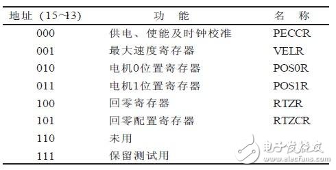
Table 1 MC33991 internal registers
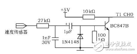
Figure 1 speed sensor signal conditioning circuit diagram
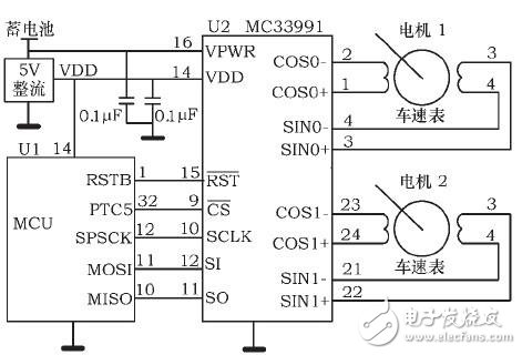
Figure 2 MC33991 and MCU interface circuit diagram
MC68HC908GR16 SPI clock pin SPSCK, host data input slave output pin MISO, host data output slave input pin MOSI and I / O pin PTC5, respectively connected to MC33991 SCLK, SO, SI, CS pin, RSTB The pin is connected to the RST pin of the microcontroller.
RJ45 We are manufacturer of RJ45 3U Gold in China, if you want to buy Gold Flash Plated,8P8C with Shield,Shield with EMI please contact us.
The connection sequence of RJ-45 line in common B standard is orange white, orange, green white, blue, blue white, green, brown white and brown. When connecting different equipment, use standard a. the connection sequence is green white, green, orange white, blue, blue white, orange, brown white and brown. Generally, the pressing method of b-mark is commonly used. If you want to make a cross line, one side is a standard, and the other side is b standard.
Working in the data link layer, the switch has a high bandwidth back bus and internal exchange matrix. All ports of the switch are connected to the back bus. After the control circuit receives the data packet, the processing port will look up the address reference table in memory to determine which port the NIC (network card) of destination MAC (hardware address of network card) is attached to. The data packet is quickly transmitted to the destination port through the internal exchange matrix. If the destination MAC does not exist, it will be broadcast to all terminals After the receiving port responds, the switch will "learn" the new address and add it to the internal MAC address table. The switch can also "segment" the network. By comparing the MAC address table, the switch only allows the necessary network traffic through the switch. Through the filter and forward of switch, the conflict domain can be effectively reduced, but it can not divide network layer broadcast, that is, broadcast domain. The switch can transmit data between multiple port pairs at the same time. Each port can be regarded as an independent network segment, and the network equipment connected to it can enjoy all the bandwidth without competing with other devices. When node a sends data to node D, node B can send data to node C at the same time, and these two transmissions enjoy the full bandwidth of the network and have their own virtual connections. If a 10Mbps Ethernet switch is used here, the total flow flux of the switch is equal to 2 × 10Mbps = 20MBps, and the total flow flux of a hub will not exceed 10Mbps when using 10Mbps shared hub. In a word, switch is a kind of network equipment based on MAC address recognition, which can encapsulate and forward data frames. The switch can "learn" the MAC address and store it in the internal address table. By establishing a temporary exchange path between the originator and the target receiver of the data frame, the data frame can reach the destination address directly from the source address.
RJ45 3U Gold,Gold Flash Plated,8P8C with Shield,Shield with EMI
ShenZhen Antenk Electronics Co,Ltd , https://www.atkconnectors.com