Vibration is one of the most common phenomena in nature. From the universe to the atomic particles, there is vibration. In the field of engineering technology, vibration phenomena abound, but in many cases vibration is harmful. For example, vibration reduces machining accuracy and smoothness, exacerbates fatigue and wear of structural parts, and vibration of body and structural parts in vehicles and aerospace. It will not only affect the driver's operation and comfort, but also cause the body and structural parts to break or even disintegrate under severe conditions.
A vibration sensor is a sensor for detecting an impact force or an acceleration. A piezoelectric device that generates a charge by applying a stress is generally used, and a sensor that can be detected by other materials and methods is also used.
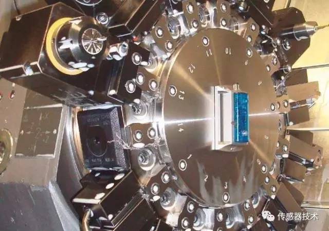
Vibration sensors can be used for vibration and displacement in machinery, long-term monitoring of thermal expansion of rotors and casings; on-line automatic detection and automatic control of production lines; measurement of various small distances and small movements in scientific research. Vibration sensors are widely used in energy, chemical, medical, automotive, metallurgy, machine manufacturing, military, scientific research and teaching.

There are many ways in which vibration sensors measure vibration, but in summary, most of the principles use the following three:
Mechanical measurement method: converts the change of engineering vibration into mechanical signal, and then performs measurement and recording after being amplified by mechanical system. Commonly used instruments include lever type vibrometer and Geiger vibrometer. This method measures frequency. The accuracy is poor, but it is very convenient to operate.
Optical measurement method: converts the amount of change in engineering vibration into an optical signal, which is displayed and recorded after being amplified by an optical system. This method is used like a laser vibrometer.
Electrical measurement method: converts the amount of change in engineering vibration into an electrical signal, which is displayed and recorded after being amplified by the line. It first converts the amount of mechanical vibration into electricity, then measures it, and knows the amount of vibration according to the corresponding relationship. This is the most widely used vibration measurement method.
It can be seen from the above three measurement methods that they are all completed by three parts: vibration sensor, signal amplification circuit and display recording.
Vibration sensor classification
In terms of mechanical receiving principle, the vibration sensor has only two kinds of relative and inertial types. However, in terms of electromechanical transformation, due to different transformation methods and properties, there are many kinds of applications, and the application range is extremely wide. The sensors used in modern vibration measurement are not traditionally independent mechanical measurement devices. They are only one part of the entire measurement system and are closely related to subsequent electronic circuits.
Due to the different internal electromechanical conversion principle of the sensor, the output power is also different. Some convert the change in the mechanical quantity into the electromotive force and the change in the electric charge, and some convert the change in the mechanical vibration amount into a change in the parameters such as resistance and inductance.
In general, these amounts of electricity are not directly accepted by subsequent display, recording, and analytical instruments. Therefore, sensors for different electromechanical conversion principles must be accompanied by a dedicated measuring circuit. The function of the measuring circuit is to finally change the output power of the sensor into a general voltage signal that can be accepted by the analysis instrument and analyzed by the instrument.
In general, the vibration sensor can have the following several methods according to its function:
According to the principle of mechanical reception, it is divided into relative type and inertia type;
According to the electromechanical transformation principle, it is divided into electric type, piezoelectric type, eddy current type, inductive type, capacitive type, resistive type and photoelectric type;
According to the measured mechanical quantity, it is divided into displacement sensor, speed sensor and acceleration sensor.
Relative and inertial vibration sensors
The relative vibration sensor is mainly used to measure the movement of the vibrating body relative to its vibration reference point (for example, the vibration of the machine shaft relative to the machine base);
The inertial vibration sensor is mainly used to measure the movement of the vibrating body relative to the earth or the inertial space (such as the vibration of the machine base, the vibration of the ground, the vibration of the aircraft in the sky, etc.). Absolute vibration sensors are also called inertial vibration sensors because they contain inertial masses inside.
The inertial vibration sensor must be installed in contact with the vibration body to be tested. The relative sensor can be contact type or non-contact type.
Electric vibration sensorElectric vibration sensors are further divided into relative electric sensors and inertial electric electric sensors.
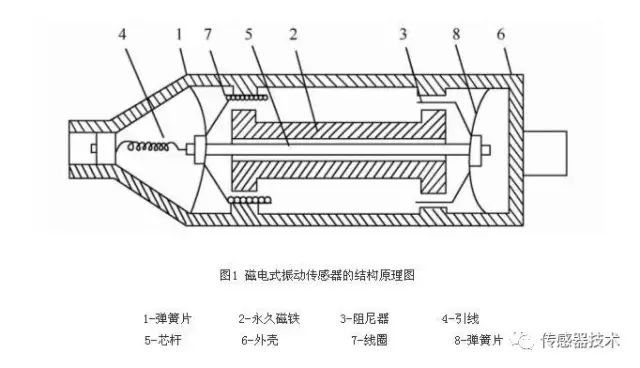
The relative electric sensor is based on the principle of electromagnetic induction, that is, when a moving conductor cuts a magnetic line in a fixed magnetic field, an electromotive force is induced at both ends of the conductor, and thus the sensor produced by this principle is called an electric sensor.

The inertial electric sensor is composed of a fixed portion, a movable portion, and a support spring portion. In order for the sensor to operate in the state of the displacement sensor, the mass of the movable portion should be sufficiently large, and the stiffness of the support spring should be sufficiently small that the sensor has a sufficiently low natural frequency.
According to the law of electromagnetic induction, the induced electromotive force is: u=BLX&r where B is the magnetic flux density, which is the effective length of the coil in the magnetic field, and r x& is the relative velocity of the coil in the magnetic field.
From the structural point of the sensor, the inertial electric sensor is a displacement sensor. However, since the electrical signal outputted by the electromagnetic induction is generated by electromagnetic induction, when the coil is relatively moved in the magnetic field, the induced electromotive force is proportional to the speed at which the coil cuts the magnetic flux.
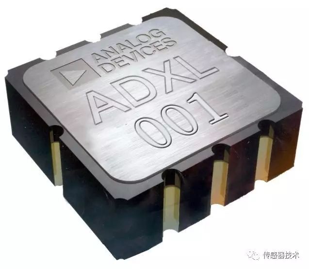
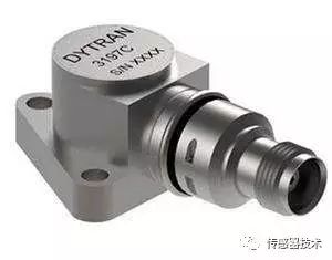
Piezoelectric vibration sensorPiezoelectric vibration sensors can also be divided into piezoelectric acceleration sensors, piezoelectric force sensors and impedance heads.
Piezoelectric acceleration sensorThe mechanical receiving part of the piezoelectric acceleration sensor is the inertial acceleration mechanical receiving principle, and the electromechanical part utilizes the positive piezoelectric effect of the piezoelectric crystal. The principle is that some crystals (such as artificially polarized ceramics, piezoelectric quartz crystals, etc., different piezoelectric materials have different piezoelectric coefficients, which can generally be found in the piezoelectric material performance table.)
When a certain direction of external force or deformation, there will be a charge on its crystal face or polarization surface, this transformation from mechanical energy (force, deformation) to electrical energy (charge, electric field) is called positive piezoelectric effect . The transformation from electrical energy (electric field, voltage) to mechanical energy (deformation, force) is called the inverse piezoelectric effect.
Therefore, by using the piezoelectric effect of the crystal, a load cell can be fabricated. In the vibration measurement, since the force received by the piezoelectric crystal is the inertial force of the inertial mass, the amount of charge generated is proportional to the magnitude of the acceleration, so the pressure is The electrical sensor is an acceleration sensor.
Piezoelectric force sensorIn the vibration test, in addition to measuring vibration, it is often necessary to measure the dynamic exciting force applied to the test piece. Piezoelectric force sensors are widely used because of their wide frequency range, large dynamic range, small size and light weight. The working principle of the piezoelectric force sensor is to utilize the piezoelectric effect of the piezoelectric crystal, that is, the output charge signal of the piezoelectric force sensor is proportional to the external force.

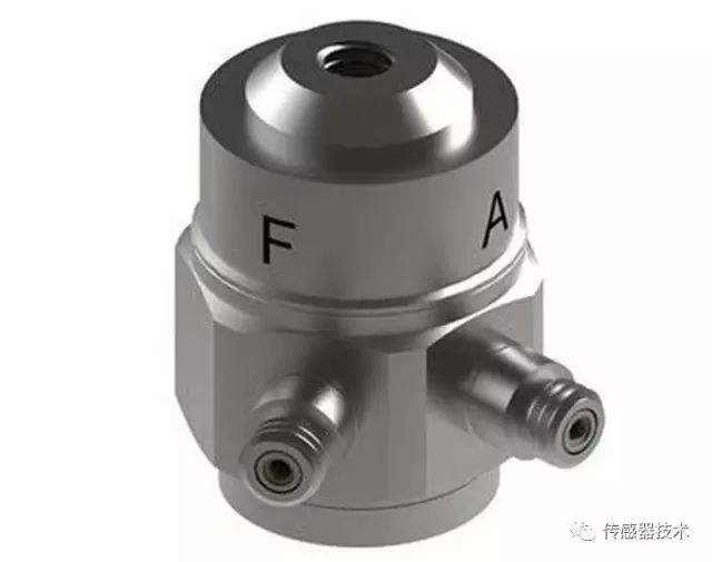
Impedance head
The impedance head is a comprehensive sensor. It integrates a piezoelectric force sensor and a piezoelectric acceleration sensor, and its function is to measure the motion response of the point while measuring the exciting force at the force transmission point.
Therefore, the impedance head is composed of two parts, one is a force sensor and the other is an acceleration sensor. The advantage is that the response of the measurement point is the response of the excitation point.
When using, connect the small head (load end) to the structure, and the big head (measurement acceleration) is connected to the force applicator of the exciter. The signal of the exciting force is measured from the "force signal output end", and the response signal of the acceleration is measured from the "acceleration signal output end".
Note that the impedance head is generally only capable of withstanding light loads and can therefore only be used for the measurement of lightweight constructions, mechanical components and material specimens. Regardless of whether it is a force sensor or an impedance head, the signal conversion components are piezoelectric crystals, so the measurement lines should be voltage amplifiers or charge amplifiers.
Eddy current vibration sensorThe eddy current vibration sensor is a relative non-contact sensor that measures the vibration displacement or amplitude of an object by a change in the distance between the end of the sensor and the object to be measured.
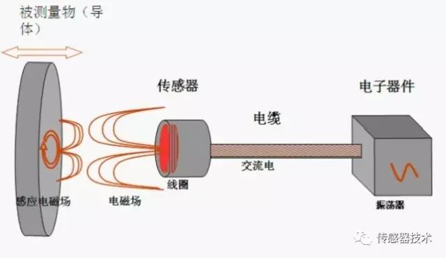
The eddy current sensor has the advantages of wide frequency range (0~10 kHZ), large linear working range, high sensitivity and non-contact measurement. It is mainly used for static displacement measurement, vibration displacement measurement, and vibration measurement of rotating shaft in rotating machinery.
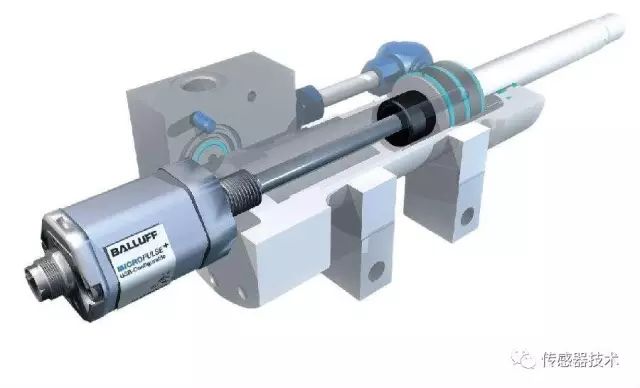
Inductive vibration sensor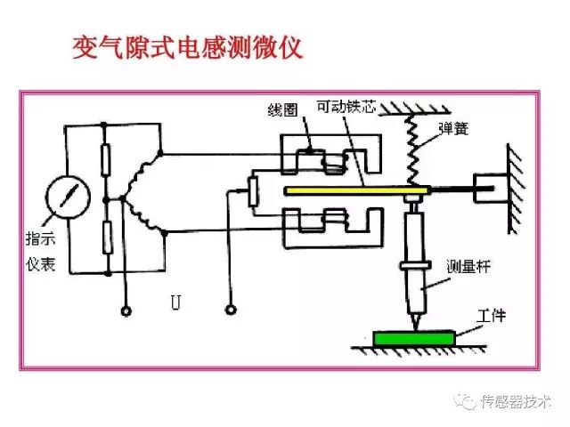
The inductive vibration sensor is a vibration sensor designed according to the principle of electromagnetic induction. The inductive vibration sensor is provided with a magnet and a magnetizer, and when the object is subjected to vibration measurement, the mechanical vibration parameter can be converted into an electric parameter signal. Therefore, the inductive sensor has two forms, one is a variable gap, and the other is a variable magnetic permeability area. The inductive vibration sensor can be applied to the measurement of parameters such as vibration speed and acceleration.
Capacitive vibration sensor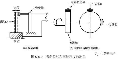
The capacitive vibration sensor obtains a variable capacitance by changing the gap or the common area, and then measures the capacitance to obtain a mechanical vibration parameter. Capacitive vibration sensors can be divided into variable gap type and variable common area type. The former can be used to measure linear vibration displacement, and the latter can be used for angular displacement measurement of torsional vibration.
Resistance strain type vibration sensorA resistive strain gauge vibration sensor converts the amount of mechanical vibration to be measured into a change in resistance of the sensing element. Sensing elements that implement such electromechanical conversion come in a variety of forms, the most common of which are resistance strain gauges.
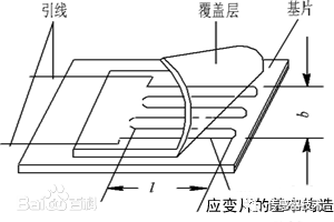
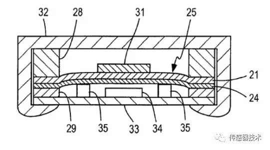
The basic structure of the strain gage is shown in the figure, which is generally composed of a sensitive grid, a substrate, a lead, a cover sheet, and the like. The sensitive grid is bent by a filament with a diameter of 0.01-0.05 mm and a high resistivity. It is actually a resistive element and is a sensitive part of the strain gauge sensing the strain of the member. The sensitive grid is secured to the substrate with an adhesive. The action of the substrate should ensure that the strain on the component is accurately transferred to the sensitive grid.
When the test piece is deformed by force, the sensitive grid of the strain gauge is also deformed, so that its resistance changes accordingly, and this resistance change is proportional to the test piece, so if it is passed through a certain measurement line The change in resistance is converted into a voltage or current change, and then the display is recorded by a display recording instrument to know the magnitude of the strain of the test piece.
Fiber optic vibration sensorWith the continuous deepening of fiber optic and optoelectronic device technology research, optical fiber sensing technology has developed by leaps and bounds. Due to its small size, light weight, high precision, fast response, wide dynamic range and fast response, the fiber sensor has good anti-electromagnetic interference, corrosion resistance and non-conductivity, so it is widely used in many fields.
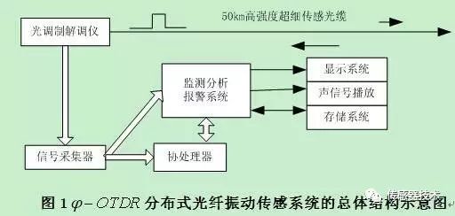
Fiber optic vibration sensors have been around for 30 years, measuring vibration signals. The original fiber-optic vibration sensor adopts an interferometric structure, and the strain of the fiber generated by the vibration causes the phase of the interferometer signal arm to change, but the structure of the sensor is complicated, which is not conducive to repeated use.
Phase modulation type fiber vibration sensorThe bit modulated fiber optic vibration sensor uses a coherent laser source and two single mode fibers. The light is split and then incident on the fiber. If the interference affects one of the two associated fibers, causing a phase difference, this phase difference can be accurately detected. The phase difference can be measured by an interferometer. There are four interferometer configurations. They include: Mach Zeder, Michelson, Fabry-Paro and Segnak interferometers.
The following is based on the principle of fiber Sagnac interference. A and B are the two sensing arms of the interferometer that function to transmit light. C is a section of fiber that is wound into a ring shape to receive or sense changes in external information. A 22 fiber 3dB coupler is used to decompose and synthesize the interference beam.
The injected light is split into two beams through the coupler, one beam from A to C to B, and finally back to the coupler; the other beam from B to C to A, and finally back to the coupler, The two beams meet to interfere.
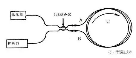
The fiber-optic Sagnac interference vibration sensor is based on an optical Sagnac interferometer and is constructed using a single-mode fiber and a 3dB coupler. The sensor is capable of detecting weak vibrations, and the output light intensity of the sensor is modulated by the signal as it propagates through the solid and acts on the sensor's sensitive components. The frequency characteristics of the signal are obtained by detecting the output light intensity and using the Fourier transform.
Light-weighted fiber optic vibration sensor
In fiber-optic communication, based on the maturity of fiber-optic coupling technology, a high-performance coupled fiber-optic acoustic vibration sensor with all-fiber device has been developed, with its measurement bandwidth, high sensitivity, low demodulation, low production cost, and ease of use. The advantages are attracted by many people.
In order to make the single-mode fiber coupler as a sensor application, the researchers analyzed the sensitive mechanism of the single-mode fiber-coupled sensor. According to the principle that the sensor coupling output has a certain relationship with the length of the coupling region of the sensor and the vibration frequency of the coupling region, it can be made. Fiber optic vibration sensor for vibration detection.
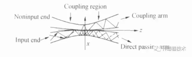
Schematic diagram of the melt tapered fiber coupler
When the incident light P0 enters the input end, as the two optical waveguides approach, the two conduction modes begin to overlap. In the coupling region of the double pyramid structure, the optical power is redistributed, and part of the optical power continues from the "through arm". The transmission is carried out by another "coupling arm" to another optical path.
The difference between the output power of the two output ends of the coupler is linear with the vibration acceleration of the excitation source. Therefore, by measuring the change in the output power of the coupler, the value of the sensor acceleration can be obtained to measure the vibration.
5 %以下。 Within the response of the sensor is very sensitive, the linear relationship of the coupling ratio is good, and the temperature drift effect can be stabilized within 0.5%. Compared with the test of the piezoelectric vibration sensor, the sensor can better realize the low frequency and 4 kHz high frequency vibration detection of 0-50 Hz.
Principle and structure of wavelength modulation optical fiber vibration sensor
The principle of wavelength modulation sensing is that the measured field/parameter interacts with the sensitive fiber, causing the wavelength of the transmitted light in the fiber to change, and then determining the measured parameter by measuring the variation of the wavelength of the light.
From the mathematical expression 3.1.3 of the center wavelength of Prague, the sensing information is obtained by the modulation of the center wavelength of the Bragg by the external parameters. This process is the sensing principle of the fiber grating.

Where, the effective refractive index of the core is, T is the period of the grating.
It can be seen from the equation that it is determined by the grating period and the effective refractive index of the reverse coupled mode. Among them, any physical process that can change these two parameters will cause the grating Bragg wavelength to drift. Of all the external factors that cause the grating Bragg wavelength drift, the most direct is the change in strain parameters.
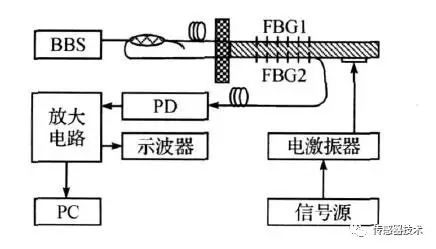
As shown in the figure below, a fiber Bragg grating vibration sensor is fixed on the package shell by one end of the mechanical suspension beam arm and connected to the object platform to be tested. When measuring vibration, the vibration source and the stage vibrate at the same time, causing the cantilever arm to vibrate.
Two identical fiber gratings, one symmetrical position mounted on the lower surface of the cantilever arm as a signal demodulation grating, and the other mounted on the upper surface of the mechanical suspension beam as a sensing grating.
The mechanical vibration of the cantilever beam is caused by the vibration inertial force, which causes the two gratings to generate periodic strain stretching or contraction, which causes the Bragg wavelength of the FBG to change. By detecting whether the information of the wavelength is consistent before and after, the vibration measurement can be realized. .
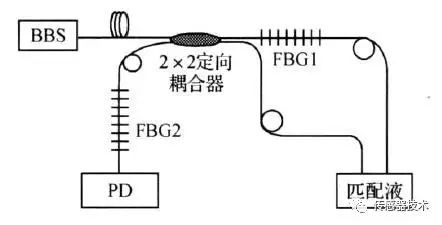
Light is sent to the sensing head 1 through a 2 x 2 fiber coupler. After that, the reflected light signal returns to the 2×2 fiber coupler, and passes through the sensing head 2. The transmitted light intensity of the sensing head 2 is photoelectrically converted, and the optical signal is converted into a vibrating electrical signal. At this time, the sensing head 2 The function is to use the optical wavelength filter of the sensing head 1 to convert the wavelength change of the sensing head 1 into a light intensity signal change.
Fiber grating vibration sensor
The fiber grating vibration sensor is characterized by a new simple and easy demodulation technology, which can effectively eliminate the å•å•¾ phenomenon of the fiber grating sensitive signal, effectively reduce the temperature cross sensitivity of the sensor, and the vibration measurement accuracy is significantly improved.
90W Medical Adapter,5V Medical Power Adapter,90W Medical Outlet Adapter,Medical Grade Power Adapter Stanstards
Shenzhen Longxc Power Supply Co., Ltd , https://www.longxcpower.com