At present, many developed countries in the world are conducting research on robot system technology solutions. The United States began the development of military robot technology and equipment from the end of the 1990s. At that time, the "future troops" plan was formulated. Within the framework of the plan, a large amount of funds was allocated - $22.5 billion for the development of military robotics equipment. Another developed power, Japan, has listed robotic technology equipment as one of the country's seven priority development directions, with the goal of becoming a world leader in robotics. The European Union also joined the competition several years ago and passed billions of military robot technology equipment plans.
Although Chinese officials have not announced plans in this area, they can find out that they are also developing military robots and other types of robotic technology equipment based on individual reports on specific projects. South Korea is also implementing a robotic technology equipment development plan. The priority strategic direction is to provide professional technical equipment for individual orderers, such as robot monitoring systems for the Near East countries.
Russia is also conducting research work in the field of military robotics. It is worth noting that our individual achievements have reached the world-class level, but in general, the current level of development is not enough, especially in the field of military robots, which is very worrying in the context of the world's weapons renewal.
As mentioned above, in the United States in recent decades, the most important development plan for the armed forces before 2030 is the Future Combat System (FCS), in which several ground robot weapon systems are to be developed. These include the fourth part of the "Future Combat System" program - "ground remote control vehicles" - UGV (UnmannedGround Vehicles - Ground Unmanned Vehicles).
According to the Military Resources (MilitariResurs) magazine (No. 11 of 2015), in the future, (United States) will develop:
Armed Robot Vehicle (ARV-ArmedRoboticVehicle): Reconnaissance (Reconnaissance, Surveillance and Target Acquisition-RSTA) and Assault direction;
Multifunctional Utility Logistics and Equipment platform-MULE: reconnaissance, engineering and transportation vehicles;
Small-calibre unmanned vehicle (SmallUnmannedGroundVehicle-SUGV).
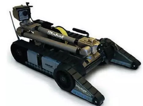
Local war experience in recent years shows that the plan has begun to be put into practice. Among them, since 2010, the engineering robot PackBot (Figure 1) began to participate in military operations in Afghanistan and Iraq. The robot weighs 20 kilograms and has a tracked chassis that can cross obstacles and rugged terrain. The robot can perform 600 to 700 operations in a single day, and its functions include regional mine clearance, laying lines, and participating in combat operations.

Figure 1. Outline layout of the PackBot Engineer Robot
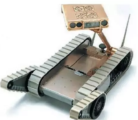
iRobot and Boston University have jointly developed a robot whose main task is to find enemy snipers. The device name is REDOWL (Robotic Enhanced Detection Outpost WithLasers) (Figure 2). The robot is able to search for snipers and perform fast shooting with the built-in camera. The robot is equipped with a laser range finder, a thermal finder, a sound source calibration machine, 4 independent cameras and a GPS receiver. The robot can find the location of the sniper based on the sound of the shot, with a probability of 0.9. The software of REDOWL (Red Owl) is capable of filtering out false sound signals.

Figure 2. REDOWL reconnaissance robot shape layout
1.0mm (.039″) Pitch Pin Headers
Overview
Antenk offers a variety of high quality and competitively priced 1.0mm pitch single, dual, three, quad row pin (male) headers used in many board-to-board PCB connections, fitting small-sized, densely-packed devices.
This low-profile component is made from high-temperature thermoplastic and is offered with several means of connections and mounting styles such as through-hole (THM) or surface mount (SMT) and can be in vertical (straight), elevated or at a right angle configuration/orientation dissipating current of about 1.0 A or less.
The pin (male) header is generally mated with receptacle or stackable header connectors (female sockets). This types of pin headers are suitable for PCB board to board connection or for signal transmission application.
Applications of 1.0mm Pitch Pin Headers
Its small size is most suitable for PCB connections of small equipment and devices such as WiFi equipment, gaming consoles, measurement instruments, and other equipment in need of a special interface to become interconnected
Mount Type: Through-hole vs Surface Mount
At one side of this pin header is a series of pins which can either be mounted and soldered directly onto the surface of the PCB (SMT) or placed into drilled holes on the PCB (THM).
Through-Hole (Poke-In)
Best used for high-reliability products that require stronger connections between layers.
Aerospace and military products are most likely to require this type of mounting as these products experience extreme accelerations, collisions, or high temperatures.
Useful in test and prototyping applications that sometimes require manual adjustments and replacements.
1.0mm vertical single row header, 1.0mm vertical dual row header, 1.0mm Elevated single row pin header, 1.0mm Elevated dual row pin Header, 1.0mm Right-angle single row header and 1.0mm Right-angle dual row header are some examples of Antenk products with through-hole mount type.
Surface-Mount
The most common electronic hardware requirements are SMT.
Essential in PCB design and manufacturing, having improved the quality and performance of PCBs overall.
Cost of processing and handling is reduced.
SMT components can be mounted on both side of the board.
Ability to fit a high number of small components on a PCB has allowed for much denser, higher performing, and smaller PCBs.
1.0mm Right-angle Dual Row pin header, 1.0mm SMT Single row pin header, 1.0mm SMT Dual row pin header and 1.0mm Elevated Dual Row Pin Header are Antenk`s SMT pin headers.
Soldering Temperature for 1.0mm Pitch Pin Headers
Soldering SMT pin header can be done at a maximum peak temperature of 260°C for maximum 60 seconds.
Pin-Type: Vertical (Straight) and Right-Angle
1.0mm pitch headers may be further classified into pin orientation as well, such as vertical or straight male header or right-angle male header.
Vertical or Straight Pin (Male) Header Orientation
One side of the series of pins is connected to PCB board in which the pins can be at a right-angle to the PCB surface (usually called "straight" or [vertical") or.
Right-Angle Pin (Male) Header Orientation
Parallel to the board's surface (referred to as "right-angle" pins).
Each of these pin-types have different applications that fit with their specific configuration.
PCB Connector Stacking
Elevated Pin Header Orientation
Elevated pins aka Stacked Pins or Mezzanine are simply stacked pin headers providing an exact distance requirement between PCBs that optimizes electrical reliability and performance between PCB boards.
Profile Above PCB
This type of configuration is the most common way of connecting board-to-board by a connector. First, the stacking height is calculated from one board to another and measured from the printed circuit board face to its highest insulator point above the PCB.
Single, Dual or Multiple Number of Rows
For a 1.0mm straight or vertical male pin header, the standard number of rows that Antenk offers ranges from 1 to 2 rows. However, customization can be available if 3 ,4 or n number of rows is needed by the customer. Also, the number of contacts for the single row is about 2-50 pins while for dual row, the number contacts may vary from 4-100 pins.
Pin Material
The pins of the connector have been designed with copper alloy. With customer`s demand the pins can be made gold plated.
Breakaway design
The pin headers are also equipped with a breakaway design making them fully compatible with their female receptacles.
Custom 1.0mm Pitch Pin Headers
Customizable 1.0 mm pitch pin headers are also available, making your manufacturing process way faster as the pins are already inserted in the headers, insulator height is made at the right size and the accurate pin length you require is followed.
Parts are made using semi-automated manufacturing processes that ensure both precision and delicacy in handling the headers before packaging on tape and reel.
The tape and reel carrier strip ensures that the headers are packaged within accurately sized cavities for its height, width and depth, securing the headers from the environment and maintaining consistent position during transportation.
Antenk also offer a range of custom Tape and reel carrier strip packaging cavities.
Male Header Pins,1.0Mm Male Header,1.0Mm Pin Header,1.0Mm Male Header Pins, 1.0mm THM Male Header, 1.0mm SMT Male Header
ShenZhen Antenk Electronics Co,Ltd , https://www.antenk.com