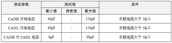
The CAN CAN bus design specification has strict regulations on the input capacitance of the CAN node. Each node is not allowed to add too many capacitive devices. Otherwise, when the nodes are combined, the bus waveform will be distorted and communication errors will increase. The details are shown in Table 1. Test the input capacitance standard in the standard GMW3122 for automotive
This article refers to the address: http://
Table 1 GMW3122 Input Capacitor Standard
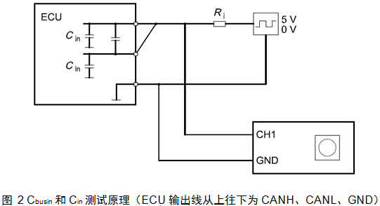
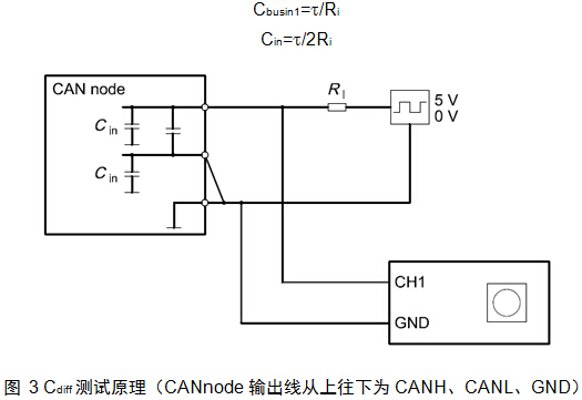
Therefore, each manufacturer must test CANH to ground, CANL to ground, CANH to CANL input capacitance of CAN node DUT (device under test) before boarding. The method is generally to use the CAN method in the GMW3122 automotive test standard. as the picture shows.
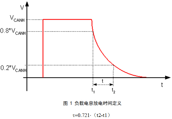
Such a test method has a relatively large limitation. It can only be measured and calculated by the discharge time of a waveform. The artificial error is large, and it is time consuming to pass multiple statistics and then average. In addition, since the capacitor is a nonlinear device, the square wave measurement cannot effectively eliminate the DC component.
Therefore, Guangzhou Zhiyuan Electronics Co., Ltd. improved the test method. After combining the CANScope-Pro bus analyzer with the CANScope-StressZ expansion board, the test waveform is sent as a sine wave, and the test accuracy is higher than the square wave. It is not affected by the internal resistance of the transceiver and the cable, and no load resistor is required. And it can be automatically measured, reducing manual errors and workload.
1. Test Сin
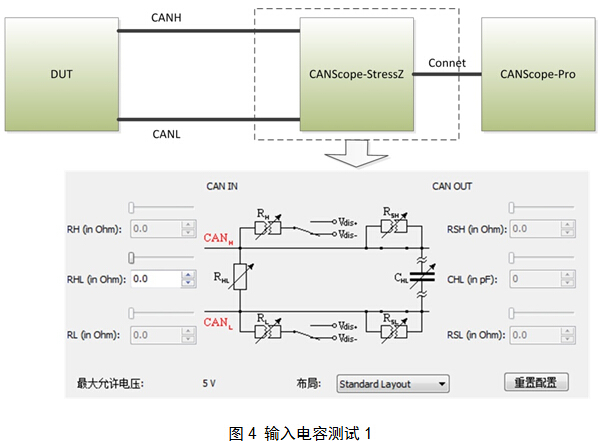
As shown in Figure 4, a test connection is made. Note that the termination resistor RHL is set to 0Ω, which shorts the CANH and CANL.
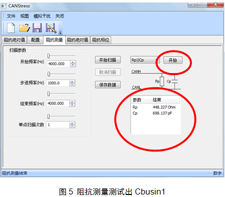
If Cin is between 40 and 150 pF, the Cin test passes.
2. Test Cdiff
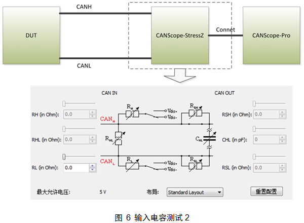
As shown in Figure 6, the test connection is made. Note that the RHL termination resistor is disconnected and the RL is enabled, set to 0Ω and then connected to Vdis-.
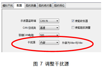
Turn on the CANStress configuration and make the interference source internal. Ensure that the CANL is shorted to ground. As shown in Figure 7.
As shown in Figure 8, click on the start of the impedance measurement, the tested Cp is Cbusin2, then Cdiff = Cbusin2 - Cin.
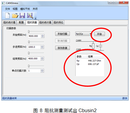
If the Cdiff is between 0 and 90 pF, the Cin test passes.
CANScope Analyzer Guangzhou Zhiyuan Electronics Co., Ltd. develops a comprehensive CAN bus development and testing professional tool, integrating mass storage oscilloscope, network analyzer, bit error rate analyzer, protocol analyzer and reliability test tool. And organically integrate and correlate various instruments; redefine the development and test methods of CAN bus, which can evaluate the correctness, reliability and rationality of CAN network communication in multiple angles; help users quickly locate faulty nodes and solve them. The various problems of CAN bus application are the ultimate tools for CAN bus development and testing.
Parallel Kits,Inverter Parallel Kit,Inverter Kit For Generator,Inverter Generator Parallel Kit
Easun Power Technology Corp Limited , https://www.easun-power.com