A VLAN is a logical network that is divided on a physical network. This network corresponds to the second layer network of the OSI model.
The division of VLANs is not limited by the actual physical location of the network ports;
VLAN has the same properties as a normal physical network;
The second layer of unicast, broadcast, and multicast frames are forwarded and spread in one VLAN without directly entering other VLANs.
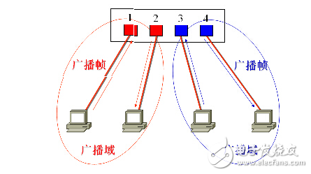
After receiving the broadcast frame, the switch forwards only to other ports that belong to the unified vlan.
After the broadcast domain is separated, the VLAN can control the broadcast storm in a VLAN. After the VLAN is divided, as the broadcast domain shrinks, the bandwidth consumed by the broadcast packets in the network is greatly reduced, and the network performance is significantly improved.
Data transmission between different VLANs is implemented through the third layer (network layer) routing. Therefore, using VLAN technology, a data link layer and a network layer switching device can be used to build a secure and reliable network.
At the same time, since VLANs are logical rather than physical, geographical restrictions can be avoided when planning the network.
VLAN division methodPort-based VLAN (Port-Based)
Protocol-based VLAN ( Protocol-Based )
MAC-Layer Grouping based on MAC layer grouping
Network layer grouping based VLAN (Network-Layer Grouping)
IP Multicast Packet Based VLAN (IP MulTIcast Grouping)
Policy-based VLAN ( Policy-Based )
Port-based static VLAN
Port-based static VLANs are the simplest and most efficient way to partition a virtual LAN. It is actually a collection of ports on a switch. Network administrators only need to manage and configure the ports of the switch, regardless of what devices are connected to the switch port. This method of dividing VLANs is divided according to the ports of the Ethernet switch, and is the most widely defined method in the industry. IEEE 802.1Q specifies this international standard for VLAN division.
The port-based VLAN consists of two steps in its implementation:
1. First enable the VLAN (identified by the VLAN ID);
2. Then assign the switch port to the corresponding VLAN;
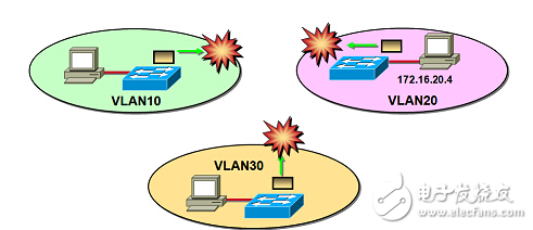
Isolated broadcast domain
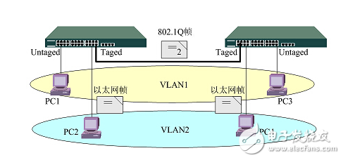
The port-based VLAN (Port VLAN) implements logical division of the switch by port VLAN ID. The broadcast domain is limited to the port set of the same VLAN, and different VLANs cannot communicate directly. After a VLAN is configured on multiple switches, you can use the trunk (trunk) mode to implement intra-VLAN communication across switches. The trunk port of the switch does not belong to a VLAN, but can carry frames of all VLANs.
This implementation of cross-switch VLAN technology used frame filtering early, and current international standards require frame marking. The logical structure of network management can be completely independent of the actual physical connection, greatly improving the flexibility of networking.
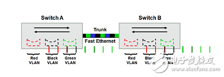
What is a trunk?The so-called trunk is used to connect between different switches to ensure that members of the same VLAN established across multiple switches can communicate with each other. The ports used for interconnection between switches are called trunk ports. The word Trunk is the meaning of a trunk or a trunk, but it is generally not translated, and the original text is used directly.
Note: Unlike general switch cascading, Trunk is based on the second layer of OSI.
Configure a trunk mode between the switches or between the switch and the router. The trunk port is a trunk port. When the same port transmits different VLAN information, you need to set a trunk. This allows data frames belonging to different VLANs to pass through. This relay link is transmitted.
There are two formats for frames:
ISL: Inter-Switch Link, a protocol unique to Cisco switches;
IEEE 802.1Q: is an international standard protocol that is supported by almost all network equipment manufacturers;
By default, the data of all VLANs existing on the switch is forwarded on the trunk.
IEEE 802.1Q standard
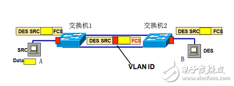
IEEE 802.1Q uses a 4 Byte header to define a Tag. The Tag header includes a 2 Byte VPID (VLAN Protocol IdenTIfier) ​​and a 2 Byte VCI (VLAN Control InformaTIon).
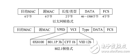
Based on the 802.1Q Tag VLAN, the VID is used to divide different VLANs. When the data frames pass through the switch, the switch identifies the VLANs in which they are located according to the VID information of the tags in the data frame. (If there is no tag header in the frame, the port through which the frame passes is applied. The default VID to identify the VLAN they are in). This causes all data frames belonging to the VLAN, whether unicast frames, multicast frames or broadcast frames, to be restricted from being transmitted in the logical VLAN. After a VLAN is configured on multiple switches, you can use the trunk mode to implement intra-VLAN communication across switches. The trunk port of the switch does not belong to a VLAN but can carry frames of all VLANs.
In the VLAN configuration, we can use the switchport mode command to specify the mode of a switch port. You can specify the interface as an access port or a trunk port (the default is access).
If the mode of a switch port is access, the interface can only be a member of a VLAN. This interface is also called a port VLAN.
If the mode of a switch port is trunk, the interface can be a member of multiple VLANs. This configuration is called a tag VLAN.
By default, the trunk interface can transmit all the VLANs supported by the switch (1~4094). However, you can also restrict the traffic of some VLANs from passing through this trunk port by setting the license VLAN list of the interface.
Harsh Environment Membrane Switch
here are several elements and environmental conditions that can cause potential problems for Membrane Switch technologies, including:
Outdoor exposure to sunlight and UV rays
Exposure to harsh chemicals and/or solvents
Operator (mechanical) abuse
Dust and debris, often a problem for devices used outdoors
Extreme humidity
Extreme temperatures, both hot and cold
Atmospheric pressure at high altitudes
Moisture ingress
For this reason it is essential that your membrane switch supplier offer creative solutions to these challenges, both through unique switching technologies such as:
Dynapic Piezoelectric keypads and
DuraSwitch PushGate products.
Much of the process in designing membrane switch technologies for harsh environments involves selecting the appropriate materials and components to provide the protection necessary to ensure the integrity of each component within the membrane switch assembly.
The key considerations are choosing durable materials for the graphic overlay and selecting pressure-sensitive adhesives with the ability to withstand potential contaminants and other elements that could impact performance. A special adhesive sealing process can also be used to create an impervious bond that`s unaffected by the harsh conditions that would ordinarily cause device failure.
There are a range of options when it comes to durable materials and components capable of standing up in harsh, abusive, or rugged environments.
Harsh Environment Membrane Switch,Short Cable Membrane Switch,Heat-Resistant Membrane Switch,Round Button Membrane Keypad
Dongguan Nanhuang Industry Co., Ltd , https://www.soushine-nanhuang.com