Many FM transmitter circuits have been published here. This is just one after the other, a simple two-transistor tuning. The first stage of the circuit is based on a pre-stage of transistor Q1. This is a basic bias amplifier stage collector current with R1 providing the necessary collector-to-base bias resistor R2 set for the collector. C1 is the base input audio signal of the input DC decoupling capacitor couple Q1. C8 is the power supply bypass capacitor. The next stage is around the transistor Q2 oscillator and modulation stage. The output electrolytic capacitor C2 couples the first stage to the second stage. Q2 bias resistors R3 and R4. R5 is the emitter resistance of Q2. The inductor L1 and the trimmer capacitor C5 form a resonant circuit, which is necessary to create an oscillation. The modulated FM signal is at the collector of Q2, which uses a capacitor C9 to couple the antenna.
Circuit diagram.
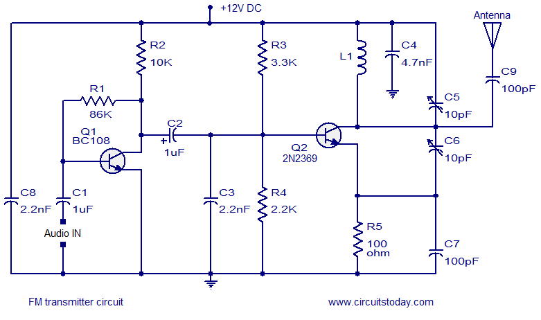
Simple FM transmitter circuit
Precautions.
The circuit can be powered from any 6 to 12V DC.
Use battery-powered circuitry to improve performance and reduce noise.
A 9V PP3 battery is a good choice.
If you are using battery elimination, then it must be well filtered and regulated.
Fine-tuning C5 can be used to adjust the transmission frequency.
The antenna can be a 1 meter copper wire.
L1 can build the number of turns of the first 4 1mm enameled wires of a 10mm diameter plastic.
The maximum range obtained by the trimmer capacitor C6 can be adjusted.
The components required for this circuit can be sourced from the trash.
Annealing Machine,Pv Copper Strip Annealing Machine,Pv Copper Strip Annealing Equipment,Annealing Heat Treatment Machine
Jiangsu Lanhui Intelligent Equipment Technology Co., Ltd , https://www.lanhuisolar.com