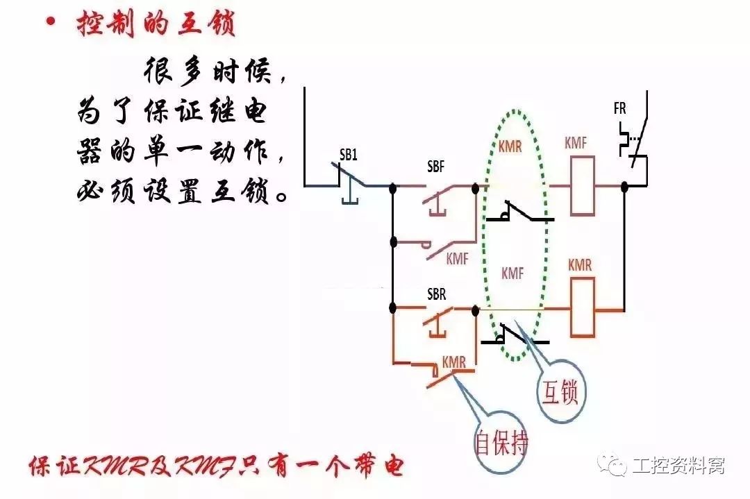
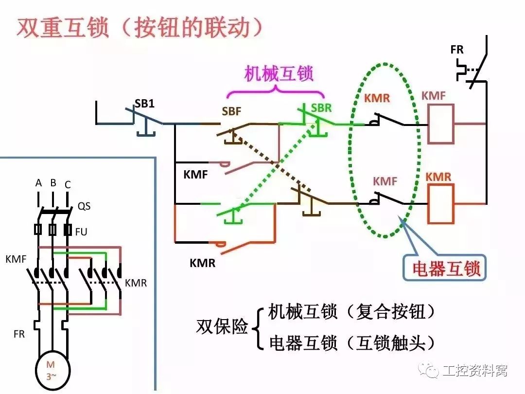
The secondary circuit mainly refers to the secondary equipment that monitors, controls, regulates and protects the working conditions of the primary equipment, and is connected to form a circuit according to certain requirements, which is called a secondary circuit. The drawing describing the secondary circuit is called a secondary circuit diagram. The secondary circuit generally includes: a control loop, a signal loop, a measurement loop, an automatic device loop, and the like.
Since the logic of the secondary circuit diagram is very strong and is drawn according to a certain law, it is easier to understand when grasping the picture.
Look at it once, then look at it again. After watching the exchange, look at the DC. AC look at the power supply, DC line-up diagram The coil corresponds to the contact, the contact is drilled into a line. The order is up, down, left and right, and the off-screen equipment is connected. ——The long-awaited picture port
The first step: look at it once and see it twice.
Once: circuit breakers, disconnectors, current, voltage transformers, transformers, etc. Understand the functions of these devices and the commonly used protection methods, such as transformers generally need to install over current protection, current quick-break protection, overload protection, etc., master the basic principles of various protection; then find the conversion and transmission components of primary and secondary equipment, The effect of one change on the second change.
Step 2: After watching AC, see DC
First look at the AC circuit of the secondary diagram, as well as the characteristics of the electrical quantity change, and then find the "fruit" of the DC loop from the "cause" of the AC quantity. The general AC loop is simpler.

The third step: AC to see the power, DC to find the coil
The AC circuit generally starts from the power supply and contains two parts: the AC current and the AC voltage loop. First, find out which current transformer or which group of voltage transformers are used to supply power (current source, voltage source), and the converted current and voltage. The role, their relationship with the DC loop, and the corresponding electrical quantity are reflected by which relays.
The fourth step: the coil corresponds to the contact, the contacts are connected into a line
After finding the coil of the relay, find the loop where the corresponding contact is located. Generally, the contact is connected to another loop. In this loop, other relay coils may be connected in series, which is caused by the coils of other relays. Its contacts are connected to the other circuit until the logic function preset in the secondary circuit is completed.

Step 5: Look up and down, left and right, and then the off-screen device
Mainly for the expansion diagram, terminal diagram and post-screen equipment installation diagram. In principle, it is viewed from the top to the bottom and from the left to the right, together with the equipment outside the screen.
Remember these 5 jingles, then the next question can be solved easily!
Omni-Directional Antenna, that is, in a horizontal direction on the drawing performance for 360 "uniform radiation, omnidirectional is usually said. Normally lobe width is smaller, the greater the gain. Omni-directional antenna application in communication system in general, the closer range is big, the price is cheap. Gain general under 9 db. Shown below for the omni-directional antenna signal radiation pattern.
Omni Directional Antenna for TV,Omni Directinal Wifi,Omni Directinal Outdoor,Omni directinal Indoor,Omni Directional HD Antenna
Yetnorson Antenna Co., Ltd. , https://www.yetnorson.com