The role of the GPS receiving antenna is to convert the electromagnetic wave energy of the radio signal emitted by the satellite into the current that the receiver electronics can ingest. The size and shape of the antenna is important because these features determine the ability of the antenna to acquire weak GPS signals. The antenna can be designed to operate on a single L1 frequency or on both L1 and L2 frequencies, as needed. Since the GPS signal is a circularly polarized wave, all receiving antennas are circularly polarized (since the ground antenna signal is polarized with the polarization direction of the satellite antenna as the reference. For circular polarization, only the satellite is aligned , you can receive a satisfactory TV image signal, no need to adjust the polarization direction.) Working mode. Despite the wide variety of conditions, there are many different antenna types, such as unipolar, bipolar, helical, quadrilateral helical, and microstrip antennas.
There are two types of built-in antennas for GPS receivers - flat antennas and four-arm helical antennas.Patch Antenna
Flat antennas have become the most popular type of antennas due to their durability and relative ease of fabrication. The shape can be round or square or rectangular, like a copper-clad printed circuit board. It consists of one or more metal pieces, so the most common shape of a GPS antenna is a block-like knot, like a biscuit. Because the antenna can be made small, it is suitable for aerospace applications and personal handheld applications.
Another major feature of the antenna is the gain pattern, or directionality. The directionality of the antenna can be used to improve its resistance to dry and multipath effects. In the precise positioning, the stability of the phase center of the antenna is an important indicator. When the satellite antenna is directly above the antenna, the signal gain is the largest, which has two problems:
1. The receiving range of the tablet is above the flat plate, and the flat plate should face the sky, which will cause trouble for the handheld and the car. 2. Although the satellite signal on the top of the head is better, it is easier to lock, but if there is no satellite with low angle, the error will be relatively high and the accuracy will be very poor. So based on these shortcomings, a four-arm helical antenna was used on the GPS receiver.
Quadrifilar Helix Antenna
The four-arm helical antenna consists of four specific curved metal lines. No grounding is required. It has the characteristics of a Zapper antenna and the characteristics of a vertical antenna. This clever structure allows the antenna to have a gain of 3dB in any direction, increasing the time it takes for satellite signals to be received. The four-arm helical antenna has a full 360-degree receiving capability, so when combined with the PDA, the four-arm helical antenna can receive regardless of the placement position of the PDA, which is different from the flat-panel GPS antenna. Good reception limit. With this type of antenna, when the satellite appears at 10 degrees above ground level, it can receive the signal transmitted by the satellite.
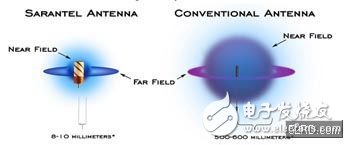
However, if there are many sources of interference near the ground receiving station, the four-arm helical antenna is not applicable because the four-arm helical antenna has a horizontal gain, which amplifies the noise together and interferes with the reception of the satellite signal. But the four-armed helical antennas produced today can break through the limitations of many conventional antennas. The antenna is made of ceramic, the near field is very small, only about 3~5mm, and some conventional antennas are even up to 1m in the near field. The smaller the near field, the less the human body will cause interference when the user holds the GPS device.
Incremental encoders provide speed, direction and relative position feedback by generating a stream of binary pulses proportional to the rotation of a motor or driven shaft. Lander offers both optical and magnetic incremental encoders in 4 mounting options: shafted with coupling, hollow-shaft, hub-shaft or bearingless. Single channel incremental encoders can measure speed which dual channel or quadrature encoders (AB) can interpret direction based on the phase relationship between the 2 channels. Indexed quadrature encoders (ABZ) are also available for homing location are startup.
Incremental Encoder,6Mm Solid Shaft Encoder,Hollow Rotary Encoder,Elevator Door Encoder
Jilin Lander Intelligent Technology Co., Ltd , https://www.jllandertech.com