Radio frequency identification (RFID) RFID (radio frequency idenTIfiesTIon) is a non-contact automatic identification technology that emerged in the 1990s. It can realize the automatic identification of recognized objects by utilizing the transmission characteristics of its radio frequency signal space. The identification process does not require physical contact, does not require optical visualization, and can be recorded and processed without manual management. RFID technology can be used to identify moving targets and multiple targets. At the same time, electronic tags can be read and written, can carry a large amount of data, have strong confidentiality, and have strong environmental adaptability that is not afraid of stains and dust. It is precisely because of these other advantages that other methods can't match. RFID technology has a wide range of applications and great development prospects in the fields of production, logistics, transportation, transportation, medical care, and anti-counterfeiting. In the RFID system, the RF reader is the key device for sending the information to the background information processing system after identifying the tag, which plays an important role in ensuring the reliable operation of the RFID system. This article will design an RFID RF reader with AT-MEGA162 MCU as the controller based on Philips' MF RC500 chip. It can perform all the operations of reading, writing and controlling the Mifare one card, and can also be easily embedded into other systems (such as access control, charging) to become part of the user system.
1 RFID basic principles and system componentsRFID systems generally consist of electronic tags, readers, and back-end computers. Electronic tags, also known as radio frequency tags, transponders or data carriers; readers are also known as read heads, communicators or readouts (depending on whether the electronic tag can wirelessly overwrite data). Between the electronic tag and the reader, the space (no contact) of the radio frequency signal is realized by the nuisance component; in the coupling channel, the energy transfer and the data exchange are realized according to the timing relationship, and then read by the background computer. The data read by the writer is stored and managed and analyzed. The basic composition of the trio R FID system is shown in Figure 1.
The basic components of the RFID system
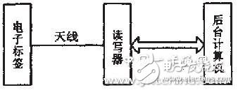
Figure 1 Basic structure of the RFID system
During system man-hours, the reader emits electromagnetic waves in an area (the size of the area depends on the operating frequency and antenna size). The tag has an LC series resonant circuit with the same frequency as the reader. When the electronic tag passes through the electromagnetic wave effective area of ​​the reader, the LC resonance circuit in the tag generates resonance under the excitation of the electromagnetic wave, thereby generating an induced charge. When accumulated to a certain extent, the capacitor can be used as a power source to provide a working voltage for other circuits. After the data in the card is transmitted or received, the data reader of the reader receives the data of the card, decodes and performs error check to determine the validity of the data, and then passes RS-232, RS-422, rs-485. /' target='_blank'>RS-485 or wirelessly transfer data to the background computer for data processing.
The standardization and development efficiency of RFID systems is the primary factor for the wide application of the system. At present, most companies that produce RFR products use their own standards, and there is no uniform standard in the world. Several standards for electronic labels are now available in "S010536, 5014443, IS015693 and L9018000. The most widely used is the LSO14443, which consists of four parts: physical characteristics, RF power and signal interface, initialization and anti-collision, and transmission protocol. Since the MF RC500 supports all layers of IS014443A in Philips' RFID chip, it is easy to develop the system. Therefore, the MF RC500 can greatly improve the development efficiency of the reader and form a more uniform standard.
2 reader hardware system designThe hardware circuit of RFID radio frequency reader mainly includes microprocessor AT-MEGA162, MF RC500, antenna circuit and so on. Several of the electronic tag reader chip MF RC500 is the core of the entire reader, it will complete all necessary functions of reading and writing electronic tags, including RF signal generation, modulation, demodulation, security authentication and anti-collision. The microprocessor MCU controls the MF RC500 by reading and writing the special memory registers of the MFR C501] core. The MF RC500 is actually the medium for information exchange between the MCU and the electronic tag. Data read and write on any label must be passed through MF RCS00. The MF RC500 can be controlled by transmitting different types of commands to the MF RC500.
2.1 Introduction to MF RC500 Features
The MF RC5 00 fully integrates advanced modulation and demodulation concepts with all types of passive contactless communication methods and protocols at 13.56 M Hz. The internal transmitter section can directly drive near-operating distance antennas up to 100 mm without the addition of active circuitry; the receiver section provides a robust and efficient demodulation and decoding circuit for IS014443A compatible transponder signals; The digital part processes the IS014443A frame and error detection (parity and CRC). In addition, it features clock frequency monitoring, hardware reset with low power consumption, software-implemented power-down mode, with internal address latch and IRQ lines, automatic detection of microprocessor parallel interface types, and support for validating Ware series products. Features such as the fast CRYPTOI encryption algorithm make the MF RC500 more suitable for reader development and high security terminals.
2.2 hardware circuit design
The hardware circuit principle of RFID radio frequency reader is shown in Figure 2. To drive the antenna, the MF RC500 provides a 13.56 MHz energy carrier through the TX, and the component 2. The transmitted data is modulated according to the setting of the register to obtain a transmitted signal. The RF card responds with load modulation of the RF field. The signal picked up by the antenna is sent to the RX pin via the twist line matching circuit. The MF RC500 internal receiver detects and demodulates the signal and processes it according to the settings of the register, and then the data is sent to the parallel interface for reading by the microcontroller. The VMID voltage generated by the internal circuit is used as the input voltage of the RX pin. In order to provide a stable reference voltage, a capacitor should be connected between the VMID pin and ground. A voltage divider resistor should be connected between the VMID and RX pins. In addition, a resistor is added between the antenna and the voltage divider resistor. Series capacitors also improve the performance of the circuit.
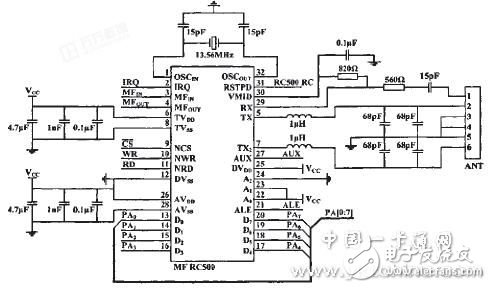
Figure 2 RFID RF reader hardware circuit schematic
2.3 Parallel interface selection of MW RC-500 and microcontroller
The MF RC50 0 supports different microcontroller interfaces, and its own automatic detection logic automatically adapts to the parallel interface of the system bus. Using the signal NCS to select the chip, after power-up or hardware reset, the MF RC500 also resets its parallel microcontroller interface mode and checks the current microcontroller interface type, identifying the logic level of the control pin after reset. Microcontroller interface. The interface type is determined by a fixed set of pin connections, as shown in Table 1. In this paper, the interface type of the multiplexed address line is selected, that is, the address and data time division multiplexing Da-D7 has a total of 8 bits of bidirectional data address bus. When ALE is high, AD will be used. The address of an ADe is latched in the internal address latch of the person, and then the read and write to the MF RC500 is completed by the signals on the NRD and NWR.
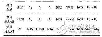
Table 1 MF RC 500 pins and interface types
MF RC 500 pin and interface type
2.4 ATMEGA162 peripheral circuit design
The RFID reader is controlled by the AVR series ATMEGA162 microcontroller. ATMEGA162 MCU comes with 8 external memory data/address lines, address latch ALE and WR, RD, which can be easily connected directly to ALE, NWR and NRD of RC500. In addition, it also has three external interrupts, two serial ports, SPI interface, etc., rich in hardware resources, easy to expand the function of the reader, leaving plenty of room for the multi-function integrated design of the reader. The peripheral circuit principle of ATMEGA162 is shown in Figure 3. 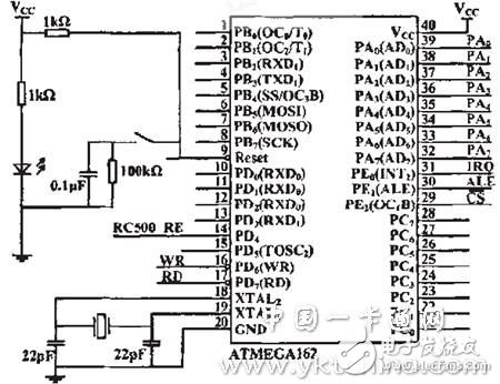
Figure 3 ATMEGA 162 peripheral circuit schematic
3 reader software system designThe control program of the MCU is mainly to initialize the MFR C500; read, write, password verify, erase, etc. of the IC card; interrupt processing with the MF RC-500 communication. This article mainly introduces the initialization of the MF RC500 using a single-chip microcomputer, that is, the operation of key registers.
3.1 Setting of key registers
In order to make the reader work normally and complete the basic data transmission and reception functions, the registers involved are: page register, command register, transmission control register, FlFO data register, interrupt enable register, InteruptRq two registers, and so on. The 7th bit of the command register, IFDetectBusy, is the interface type detection status flag. When 0, the flag interface type detection is completed. The FIFO data register is the data input and output port in the internal 64-byte FIFO buffer. The input output data stream is converted in the FIFO buffer and can be output in parallel. The Intetrupt help register is the interrupt request flag register. When the interrupt is generated, the relevant flag of the register needs to be used to determine the type of interrupt. The following is a detailed description and settings of the page register, the transmit control register, and the interrupt enable register.
3.1.1 page register
MF RC50 0 has 64 registers, 8 registers are one page, the first register of each page is page register, and its setting is shown in Figure 4. Its address is 0x00, 0", Ox10, Ox18, Ox20, Ox28, Ox30, Ox38o, its initial value is 10000000, 0x80. The page register is used to select the register page, by setting the register, you can determine the register on this page. The way of addressing.
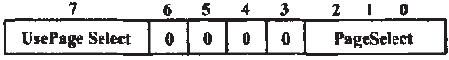
Figure 4 page register settings
The Use PageSelect bit is set to 1 to address the registers on this page. The contents of PageSelect are used as A5, A4, and A3 of the register address. These 3 bits can be addressed to 8 pages. Each page has 7 registers, which can be A2 and A1. Ao to choose. With this bit set to 0, the register address is determined by the entire contents of the internal address latch. In this paper, the address of the register is the absolute address of the register given in the MF RC500 manual, so the page register of each page is set to 0.
3.1.2 Transmit Control Register
The transmit control register is set as shown in Figure 5. Controls the two antenna pins of the MF RC500, TX1, and the type of output signal on TX2. The address is 0x11, and the initial value is 01011000, 0x58.
![]()
Figure 5 Transmit Control Register Settings
The T X2CW bit is set to 0, and the output signal on the TX2 pin is the 13.56 M Hz modulated carrier. Set TX2RFEn to 1 and output the 13.56 MHZ carrier modulated with the transmitted data on the TX2 pin. The TX1RFEn bit is set and the 13.56 MHz carrier modulated with the transmitted data is output on the TX1 pin.
3.1.3 Interrupt Enable Register
The MF RC50 0 has six interrupt sources, such as timer interrupt, transmit interrupt, receive interrupt, and idle interrupt. The interrupt request can be enabled by setting the interrupt enable register. SeTIEn is the interrupt enable bit. When this bit is set, the other interrupt control bits in this register are valid. TImerlEn, TxIEn, and Rx lEn are timer interrupt enable, transmit interrupt enable, and receive interrupt enable control bits, respectively, as shown in FIG. 6. The address of the interrupt enable register is 0x06, and the initial value is OOOOOOOO, Ox00o
![]()
Figure 6 interrupt enable register settings
3.2 System Software Design
According to the operation of the above registers, the flow of the system software design can be drawn as shown in Fig. 7. According to this process, the reader can complete a basic read and write operation on the electronic tag.
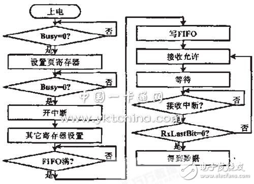
Figure 7 software flow chart
On the basis of completing the read and write operations, the system software is enriched and supplemented, so that the reader can obtain the serial number of one of the electronic tags through the anti-collision cycle in all the electronic tags in the range of the antenna field. This tag is verified and the memory is manipulated after passing. Typical operation time is less than 100ms
The RFID radio frequency reader designed in this paper fully combines the advantages of hardware and software, and can realize the reading and writing of the Mifare one card of IS014443A protocol, and the read/write distance can reach 6 cm. If the antenna system is properly designed and optimized, it can be increased to 9-10 cm. The reader can be easily connected to a serial device including a PC, and is easily embedded in other RFID applications for different application objects. Since the selected controller program storage unit is stored in Flash, it can be reprogrammed and upgraded conveniently. The reader has the advantages of low cost, fast response, stable and reliable communication, convenient operation, and the application prospect is very broad, which is of great significance to the promotion of RED.
Compact Temperature Sensor We have many products in marine temperature sensors, and our small marine temperature sensors have been traveling in various oceans. Our sensors are not only used in ship mechanical equipment, but also used in freight yards. Our small marine temperature sensor can be used to monitor the marine mechanical equipment and the temperature and humidity in the warehouse. Moreover, our sensor has been used in the oil separator module for a long time, and its performance is very stable.
Compact Temperature Sensor,Small Temperature And Humidity Sensor,Smart Temperature Sensor,Hydraulic Temperature Sensor
Taizhou Jiabo Instrument Technology Co., Ltd. , https://www.taizhoujiabo.com