0 Preface
The use of optical fiber to transmit TV programs has the advantages of frequency bandwidth, large capacity, low loss, light weight, strong anti-interference ability, high fidelity, and reliable working performance. It can not only expand the coverage of cable TV, and reduce the number of amplifiers in the transmission line. Improve the index of the entire cable TV system, and solve the problem of difficult maintenance of the amplifier of the full cable network. Optical fiber transmission network has become the main transmission method of CATV CATV network.
In an optical fiber CATV network, whether it is an analog signal or a digital signal, an optical splitter is an indispensable optical device for optical signal split transmission. With the expansion of network scale and the increase of network functions, optical fiber CATV networks are booming, and the density of optical nodes is increasing. Splitters are the most important intermediary equipment for optical node expansion. Road device. Therefore, it is absolutely necessary for us to design and calculate the optical splitter in detail. This article mainly introduces the optical index of single-wavelength single-mode optical splitter and analyzes the design and use of some optical splitters in the construction of the cable TV optical cable network project participated by the author. Helpful.
1 Main indicators of the splitter
The optical splitter is one of the most important passive devices in the optical fiber link, and its function is to divide one channel of light into multiple outputs according to a certain ratio. Optical splitters are similar to splitters and distributors in cable transmission networks. In practical applications, an optical splitter is often used to divide the optical signal output by the optical transmitter into several outputs with different strengths. The close distance, so that each optical node can get approximately equal optical power. Before designing the optical splitter, you must be familiar with the specifications of the optical splitter. The main indicators are as follows:
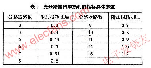
1.1 Additional loss
When the optical splitter distributes the optical signal at the input end to each branch according to a predetermined split ratio, in addition to the optical splitting loss when the optical signal passes through the optical splitter, there is also the loss caused by the optical splitter itself to the optical signal This loss is called the additional loss of the optical splitter.
The additional loss is the most basic technical indicator of the splitter, and it is intrinsically related to other performance indicators. Therefore, the additional loss not only measures the optical performance of the device, but more importantly, it is also intrinsically related to the seismic performance, temperature stability, and service life of the device. For this reason, when we select the optical splitter, we must strictly screen this index of the manufacturer.
1.2 Split ratio
The ratio of the optical splitter to the optical power distribution of each branch is called the split ratio. The split ratio is defined as the ratio of the output optical power at an output of the optical splitter to the total output optical power at the output of the optical splitter.
This index is the most important design index parameter of the optical link, which will be explained later.
1.3 Spectral ratio deviation
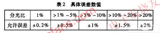
The deviation of the split ratio refers to the deviation of the actual split ratio from the design value when the splitter is manufactured. This deviation causes one light to increase and the other light to decrease. Essentially does not affect the total output power.
Since the distance between the transmitting end and each optical node is different, in order to ensure that the receiving power of the receiving end is consistent, the splitting ratio of the splitter should correspond to the transmission distance, that is, the farther the transmission distance corresponds to the greater the splitting ratio of the channel. If there is an error between the splitter actually used and the designed split ratio, it will result in inconsistent received power at the receiving end. At present, domestic manufacturers are fully capable of controlling the error of the splitting ratio of the 1 × N optical splitter within ± 0.5%.
1. 4 Spectral loss
Splitting loss: The loss caused by different splitting ratios to the optical signal is called splitting loss, and its value is -10lgK (K is the splitting ratio).
1.5 Insertion loss
Insertion loss includes splitting loss and additional loss, that is, insertion loss (dBm) = -10lgk + additional loss.
2 Design and calculation of optical network optical splitter
In the design of the HFC network fiber transmission trunk, after the fiber routing, fiber loss value, and number of optical nodes are determined, the optical power required for each fiber branch and the split ratio of the optical splitter can be designed and calculated. Calculate the optical power required for the entire optical link. When calculating the index, design in accordance with the following calculation steps.
2.1 Calculation of fiber loss value of each branch
After the fiber routing is determined, the fiber link loss value of each branch can be obtained. At present, G652 fiber is widely used in the broadcasting system. For the 1310 nm window, the G652 fiber loss does not exceed 0.35 dBm / km, and for the 1550 nm window, the G652 fiber loss does not exceed 0.22 dBm / km. For the route that has been completed, you can use an optical time domain reflectometer to measure and obtain the actual link loss value. A certain margin should be set aside for the fiber link loss value of each branch. Calculated as follows:
S = a × lN.
In the formula: S is the branch optical link loss (dBm); a is the fiber loss per kilometer; lN is the distance of each branch of the optical cable.
2.2 Receiver power of optical receiver
The optical receiver currently used has an output level range of 96 to 108 dB under the condition that the received optical power is -4 to +3 dBm. The change of the input optical power of the optical receiver has a certain influence on the system index, which can be clearly shown through theoretical calculation and practical test.
When the input optical power of the optical receiver has increased, various system indicators have been greatly improved, leaving more room for the cable distribution network. For this reason, when designing the optical cable network, the optical received power is determined to be 0 dBm ± 1 dBm.
It should be mentioned here that dBm and mw are both units of optical power, and their applications are different. They can be converted. The conversion formula is as follows:
2.3 Live connection loss
Each optical system contains a variety of optical devices, such as optical transmitters, optical receivers, optical amplifiers, etc., and these devices require FC, SC and other flanges for joints, and these movable connectors will cause some loss, These losses should be included in the total power required by the optical link. The design value of union loss is generally 0.5 dBm.
2.4 Design of splitting ratio of optical splitter
Suppose the total optical power of each channel is ∑Pn, and the optical power required by a certain channel is P1, then the split ratio K1 = P1 / ∑Pn. It should be emphasized that the optical power required by a branch is the branch fiber Link loss power plus optical receiver input optical power.
According to the optical node routing distance optimization combination grouping, use the following formula and parameters to calculate.
Calculation formula:
Where: P1, P2, P3 are the input power of each branch optical receiver, mw; PN is the output optical power of each branch of the fiber splitter, mw; PT is the output fiber power of the optical transmitter, mw; KN is The split ratio of each branch of the fiber splitter; N is the natural number 1, 2, 3 ...; a is the loss per kilometer of the fiber: a = 0.35 dBm / km (1310 nm window) and 0.22 dBm / km (1550 nm window) ; l is the length of the optical route.
According to the above formula, the N-way optical splitter can obtain the splitting ratio of each channel:
2.5 Loss calculation of each branch of optical link
After designing and calculating the splitting ratio of the optical splitter, the loss of each branch of the optical link can be calculated by the following formula. The calculation formula is:
LN (dBm) =-10Lg Kn + a × ln + additional loss + optical connector loss.
In order to ensure the long-term safe and stable operation of the network, the optical link should have a margin of 1 dBm in most cases. Therefore, the loss of each branch of the optical link should be designed as follows.
LN (dBm) =-10lg Kn + a × ln + additional loss + optical connector loss + 1.
2.6 Calculation of input optical power of splitter
According to the above parameters of each branch, the input optical power required by the optical splitter can be calculated, that is, the total power required by the real network. The total power is equal to the power loss of each branch. From this, the required power of the optical transmitter can be known, and the total power is equal to the power of the transmitter.
With the rapid development of analog and digital TV networks, and accompanying fiber-to-the-home, the frequency of optical splitters used in optical networks, the main transmission equipment of optical networks, will be greatly enhanced. Inferiority or not plays a decisive role. In the design of optical fiber CATV network, through the above detailed calculation and analysis of the optical splitter, it provides a reliable guarantee for the stable operation of the optical network.
Lamp Holder,Bulb Holder,Light Holder,Lamp Socket
WENZHOU TENGCAI ELECTRIC CO.,LTD , https://www.tengcaielectric.com