5.1.6 SelecTIO Module
Each I/O slice (I/O TIle) of Virtex-6 contains two IOBs, two ILOGICs, two OLOGICs, and two IODELAYs, as shown in Figure 5-24.
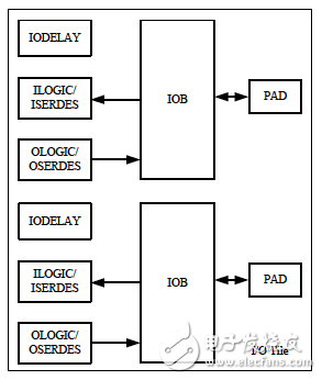
Figure 5-24 I/O slice structure
This section introduces Virtex-6's SelecTIO resources in the following areas.
(1) Electrical characteristics of SelecTIO.
(2) SelectIO's logical resources - ILOGIC resources and OLOGIC resources.
(3) SelectIO's advanced logic resources - ISERDES resources, OSERDES resources, and Bitslip.
All Virtex-6 FPGAs feature high-performance configurable SelectIO drivers and receivers that support a wide range of interface standards. Powerful features SelectIO includes programmable control of output intensity and slope as well as on-chip termination using digitally controlled impedance (DCI).
The IOB contains input, output, and tri-state SelectIO drivers. Single-ended I/O standards (LVCMOS, HSTL, SSTL) and differential I/O standards (LVDS, HT, LVPECL, BLVDS, differential HSTL, and SSTL) are supported.
Note: The differential input and VREF related inputs are powered by VCCAUX.
The connections for IOBs, pins, and internal logic are shown in Figure 5-25.
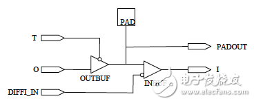
Figure 5-25 IOB, pin and internal logic connection diagram
The IOB is directly connected to the ILOGIC/OLOGIC pair, which contains input and output logic resources for data and tri-state control. ILOGIC and OLOGIC can be configured as ISERDES and OSERDES, respectively.
The Xilinx software library provides a number of I/O-related primitives that can be specified when instantiating these primitives. Primitives related to single-ended I/O include IBUF (input buffer), IBUFG (clock input buffer), OBUF (output buffer), OBUFT (three-state output buffer), and IOBUF (input/output buffer) . Primitives related to differential I/O include IBUFDS (input buffer), IBUFGDS (clock input buffer), OBUFDS (output buffer), OBUFTDS (three-state output buffer), IOBUFDS (input/output buffer), IBUFDS_DIFF_OUT (input buffer) and IOBUFDS_DIFF_OUT (input/output buffer).
Second, the logical resources of SelectIOSelectIO's logic resources mainly refer to ILOGIC and OLOGIC resources, which complete the FPGA pin to internal logic connection functions, including combined input / output, three-state output control, register input / output, register three-state output control, DDR input / Output, DDR output tri-state control, IODELAYE1 high-resolution adjustable delay unit and its control module.
The following is a brief introduction to the ILOGIC and OLOGIC functions.
(1) ILOGIC.
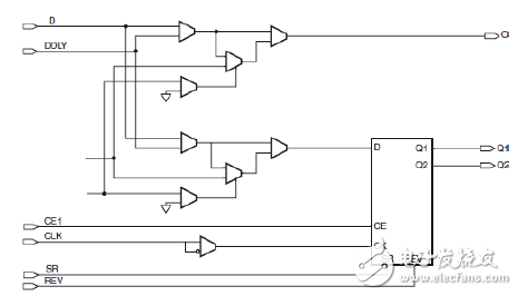
Figure 5-26 ILOGIC internal logic
The internal logic of ILOGIC is shown in Figure 5-26. The operations that can be implemented include: asynchronous/combination logic, DDR mode (OPPOSITE_EDGE, SAME_EDGE or SAME_EDGE_PIPELINED), level-sensitive latches and edge-triggered D-type flip-flops.
Asynchronous/combination logic.
Used to create a direct connection between the input driver and the internal resources of the FPGA. This path is automatically used when there is a direct (non-registered) connection between the input data and the FPGA internal logic, or when the "I/O registers/latch merges into the IOB" setting is OFF.
Enter DDR (IDDR).
Virgo-6 devices have dedicated registers in ILOGIC for input double data rate (DDR). This feature can be used by instantiating the primitives of IDDR. IDDR has only one clock input, and the falling edge data is clocked by the inverted version of the input clock (inverted in ILOGIC). The clocks of all input I/O modules are fully multiplexed, ie no clock is shared between ILOGIC or OLOGIC modules. IDDR supports the following three modes of operation:
OPPOSITE_EDGE mode, SAME_EDGE mode, and SAME_EDGE_PIPELINED mode.
SAME_EDGE and SAME_EDGE_PIPELINED are the same as Virtex-5. These modes allow designers to transfer falling edge data to the rising edge clock domain within the ILOGIC module to save CLB and clock resources and improve performance. These modes are implemented using the DDR_CLK_EDGE attribute.
Refer to Figure 5-27, Figure 5-28, and Figure 5-29 for the timing diagram for each mode.
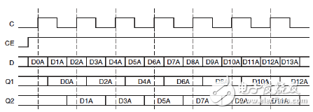
Figure 5-27 Input double data rate in OPPOSITE_EDGE mode
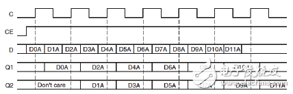
Figure 5-28 Input double data rate in SAME_EDGE mode
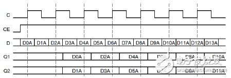
Figure 5-29 Input double data rate in SAME_EDGE_PIPELINED mode
Programmable absolute delay unit IODELAYE1.
Each I/O module contains a programmable absolute delay unit called IODELAYE1. IODELAYE1 can be connected to the ILOGIC/ISERDES or OLOGIC/OSERDES modules, or both.
IODELAYE1 is a surround delay unit with 32 taps with a scaled tap resolution. Please refer to the Virtex-6 IO User Manual on the supplied CD-ROM. IODELAYE1 can be used to combine input channels, register input channels, combined output channels or registered output channels, and can be used directly in internal resources. IODELAYE1 allows for independent delay for each input signal. The tap delay resolution can be changed by selecting the IDELAYCTRL reference clock within the range specified in the Virtex-6 User Manual. The IODELAYE1 resource can be used as an IDELAY, ODELAY, or combined delay.
.IDELAYE1 allows for independent delay for each input signal. The delay unit can be verified to an absolute delay value (TIDELAYRESOLUTION), which does not change with process, voltage and temperature changes.
The name of wireless router can be separated out of two keywords: wireless and routing. Understand the technical principle behind these two words, you understand the wireless router.
Wireless is also what we often call Wi-Fi. Wireless routers can convert home broadband from wired to wireless signals, and all devices can happily surf the Internet as long as they connect to their own Wi-Fi. In addition, these devices also form a wireless local area network, where local data is exchanged at high speed and is not limited by the bandwidth of home broadband.
For example, many people have smart speakers in their homes that can be used to control various smart appliances. When you say small X small X, turn on the TV, the speaker actually finds the TV through the LAN and sends instructions, and does not need to connect to the Internet; And if you let it broadcast news, you have to get data through the Internet.
The Local Area Network we talked about earlier, also known as the Intranet, is represented by the Local Area Network (LAN) on the router, so the Wi-Fi signal is also called WLAN(Wireless LAN); The Internet we want to access, also known as the extranet, is represented on the router by the WAN(Wide Area Network).
On the Intranet, the IP address of each device is different, which is called a private address. All devices on the Internet share the same public address, which is assigned by broadband operators such as China Telecom Unicom.
The router is the bridge between the Intranet and the external network. The above mentioned IP address translation, packet forwarding, is the router routing function.
In other words, the router is the hub of the home network, and the data of all the devices must be forwarded through it to access each other or reach the external network, which means that one husband is the key and ten thousand men are not open, so the comprehensive router is also called "home gateway".
Wireless Router,Wifi 6 Wireless Router,Mesh Wifi Router,Wifi Routers For Home
Shenzhen MovingComm Technology Co., Ltd. , https://www.movingcommiot.com