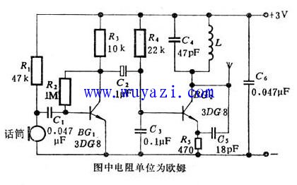
The volume is only the size of the matchbox, and its electrical schematic is shown in the figure. The inductor L is wound 5 turns on a 3 mm drill bit with a high-strength enameled wire (0.5-0.7 mm in diameter) at intervals of about 5.5 mm. The resistor uses a 1/16 watt RTX model, except for the electrolytic capacitor, and the other capacitor uses a small CC1 type ceramic capacitor. The transistor can be 3DG8 (or 3DG6), requiring β>100. Micro condenser microphones, changing the resistance R1, can change the sensitivity of the microphone (resistance R1 can be selected in the range of 10-100 kohms, high sensitivity when the resistance is large). The antenna can be replaced by a 10 cm long wire and soldered to the BG2 collector. The power supply uses two No. 5 dry batteries.
Once the components are installed, they can be debugged. The normal value of the BG1 collector voltage is around 1.4 volts. The BG2 collector current should be 4-6 mA. When debugging, do not put your hand too close to the transmitter, and use a non-inductive screwdriver for the screwdriver. The carrier signal center frequency of the transmitter is mainly determined by C4 and the inductance L. The elongated inductor L can increase the carrier frequency of the transmitter. When debugging, keep the transmitter at a distance from the FM radio, not too close, so that the radio does not pick up the carrier's higher harmonics. Tuning the FM radio, generally receiving a carrier signal from the transmitter between 80-108 MHz.
If the receiver only receives the carrier and there is no sound, the fault may be in the audio amplifier and condenser microphone. There should be 0.7-1.5 volts on the condenser microphone during normal operation. When the machine is normal, the output power can reach 5-8 mW and the launch distance reaches 100 meters.
KNB6-40 Miniature Circuit Breaker
KNB6-40 Mini Circuit breakers, also named as the air switch which have a short for arc extinguishing device. It is a switch role, and also is a automatic protection of low-voltage electrical distribution. Its role is equivalent to the combination of switch. Fuse. Thermal Relay and other electrical components. It mainly used for short circuit and overload protection. Generally, According to the poles, mini Circuit breaker can be divided into 1P , 1P+N , 2P, 3P and 4P.
KNB6-40 Miniature Circuit Breaker,Electronics Miniature Circuits Breaker,Automatic Miniature Circuit Breaker,Mini Circuit Breaker
Wenzhou Korlen Electric Appliances Co., Ltd. , https://www.zjmotorstarter.com