The calculation of the permeation/reflectivity is very common in the study of electromagnetic waves. The accuracy of the calculation results is closely related to the definition of material parameters, the selection of boundary conditions, and the meshing. The following is an experience of personal calculation of electromagnetic wave penetration / reflectivity calculations, if there are errors and omissions, please correct and correct.
Devices that need to calculate penetration/reflectivity are usually classified into several types:
Waveguide deviceFor example, various types of waveguide splitters, fiber Bragg gratings, the incident end and the exit end satisfy the waveguide mode. When the incident and exit end waveguides meet the port built-in structure (coaxial/rectangular), the built-in waveguide type can be directly selected, such as the H-bend_waveguide and the lossy_circulator case in the RF case library. When the waveguide structure is different from the built-in type, the waveguide mode needs to be first calculated by mode field analysis, coupled to the frequency domain analysis through the Numeric type of the Port boundary as the incident condition. For example, the Wave Adapter (Vave_adapter) case in V3.5a and V4, and the dielectric_slab_waveguide case updated in V4.2a, see Annex 1.
It should be noted that the waveguide often supports multiple modes. In order to ensure that the mode field distribution as the boundary condition of the frequency domain analysis is correct, the boundary mode analysis can be performed first, and multiple modes are searched, and the results are found from the results according to the mode field distribution. As the mode index corresponding to the mode of the incident condition, then the model index is used as a reference value (Search for modes around:) and the number of search modes (Desired number of modes:) is set to 1. This ensures that the incident conditions are correct.
For the above two cases, the S parameter of the port boundary can calculate the transflectivity, where S11 corresponds to the amplitude reflectivity of port 1, S21 corresponds to the amplitude transmittance from port 1 to port 2, and so on.
2. Periodic scatterersSuch as metal nano-antenna arrays, gratings, photonic crystals, have periodicity in one or two dimensions. In the RF module, the perfect electric/magnetic conductor (PEC/PMC) is the complete reflection boundary, and the scattering boundary (SBC) and port boundary are only transparent to light waves of certain angles or distributions, and the light waves of other angles will be certain. The degree of reflection, while PML is properly set to ensure that the incident waves are absorbed at all angles. It is conceivable that if the scattering field has reflections on the boundary, the resulting calculated transmission field and reflection field will be affected. The choice of boundaries is very important. Such structures can be simplified with periodic boundary conditions or with PMC/PEC boundaries based on the symmetry of the electric/magnetic field, and only the repeating units are simulated. There are two main solutions:
a). Perfect absorption layer PML for the incident and exit ends
How do you define a light source when both the incident and exit ends are set to PML?
In the V3.5a version, the transmittance and reflectivity can be calculated by integrating the energy in the incident end and the exit end as the incident condition through the internal boundary of the Port boundary. The typical case is GraTIng, and the model and description are given in Annex 2.
In the V4 version, the internal consistent method is not feasible (http://), and the light source can be defined by the background field. The transmitted power can be calculated from the total field energy flow integral at the exit end, and the reflected power can be calculated by the integral of the scattered field energy flow at the incident end.
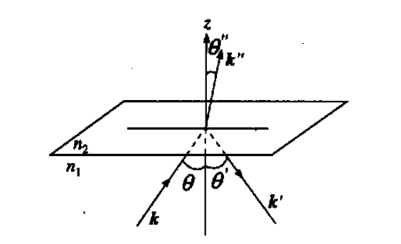
If the structure under study is the same medium at the incident end and the exit end, the background field can be directly defined as a plane wave. But when the incident and exit ends are in two media, such as a quartz plate and air interface with metal particles, electromagnetic waves are incident on the interface from the air, using a single plane wave as the background field, the PML boundary at the exit end Unreasonable reflections at this time need to define the field distribution according to the Fresnel formula, or add the calculation of the background field, see (http://).
For the case of non-uniform media, the Plasmonic Wire GraTIng case in V4 is reproduced by first calculating the background field and combining PML. When the maximum size of the mesh is 1/20 of the wavelength, the error of the calculation result of the original model Port boundary is "1%, see Annex 3. Annex 4 is the reference model given by the headquarters.
b). Multiple port boundary method
Plasmonic Wire GraTIng in the V4 model library case, according to the diffraction light of the one-dimensional grating is concentrated on the zero-order and positive-negative first-order diffraction angles, and a plurality of ports are provided on the same boundary to absorb the emitted light. However, when the scatterer is more complicated, the diffracted light may have a strong distribution at many angles, such as Bragg diffraction of the crystal under X-ray. It is not realistic to set multiple ports to achieve absorption.
3. Individual scatterers, such as metal plates with holes.The difference from the periodic structure is that the peripheral area needs to be set to PML, such as the aluminum boat scattering problem in the case library model Radar Cross SecTIon.
The above is about the definition of boundary conditions and the conditions of incidence. The PML parameters usually choose the default value. The outer side adopts the SBC boundary. The distance scatterer should be far enough. From the field distribution in the calculation result, it can be judged whether the absorption effect of PML is sufficient. Fully absorbed, the parameters need to be modified to ensure that the reflection is low enough.
In addition, the meshing of the mesh is important when simulating metal scatterers or resonator structures. Since there is a field enhancement phenomenon on the metal surface when the SPP resonance occurs, and the resonance cavity is in the same state of resonance, sufficient mesh is needed on the boundary to accurately describe the exponential decay of the field strength, for example, the silver material is in the visible light band. The skin depth is about 20 nm, and the mesh size within the skin depth needs to be much smaller than the skin depth, on the order of nm. Just as you have to see a detailed picture, you need enough resolution.
In addition, for the case of containing a metal scatterer or a gain medium, the COMSOL software defines the electromagnetic phase amplitude phase factor, when the dielectric constant or the refractive index imaginary part is negative, corresponding to the lossy medium, and vice versa. The gain medium, if set incorrectly, also creates an unnecessary error in the transmittance calculation.
A separate slip ring is a device that allows two or more rotating electrical shafts to be connected without having to pass the electricity through the shafts' bearings. This is often used in situations where there is a need to power something externally while the shaft is still turning. For example, a machine might have a drive shaft that powers it while also having a separate output shaft that needs to turn at a different speed. By using a separate slip ring, these two shafts can be powered without any interference.
Slip Ring Shaf is a key component of a slip ring. It is the shaft on which the rotary electrical contacts are mounted. The shafts must be strong enough to support the weight of the contacts and must be able to turn freely. There are many factors to consider when selecting a shaft material, including strength, corrosion resistance, and operating temperature.
Oubaibo is a professional separate slip ring manufacturer located in China. They offer a wide range of slip ring shaft made from different materials, including carbon steel, stainless steel, and brass. Their products are made to meet the highest quality standards and are backed by a 100% satisfaction guarantee.
Separate Slip Ring,Slip Ring Shaft,Slip Ring 4 Wire,Slip Ring For Motor
Dongguan Oubaibo Technology Co., Ltd. , https://www.sliprob.com