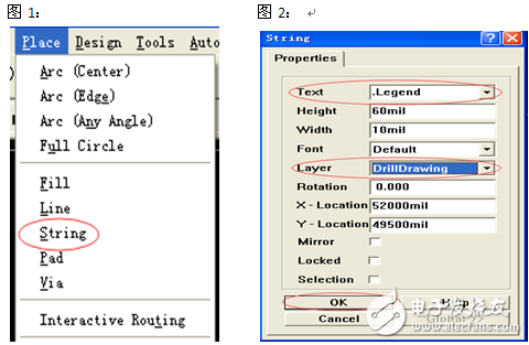
1, first open the PCB image file, it is best to check once again whether the PCB image file problems, confirm no problem after the release of the aperture marking list; toolbar: Place → String (shortcut: P + S) (Figure 1), the emergence of characters String "string" Press the Tab key to display the dialog box, select ".Legend", "DrillDrawing" and press OK (Figure 2):
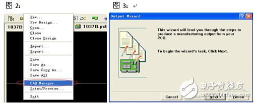
2, start Gerber, in the File → Cam Manager (Shortcut: F + M) (Figure 2), the Output Wizard output Gerber Wizard (Figure 3):
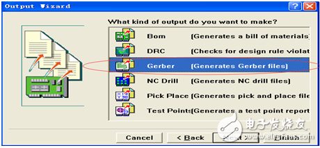
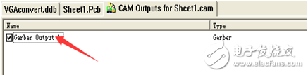
3. Press Next to proceed to the next step and select the options in the red box (below):
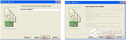
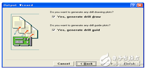
4, press Next and then two steps directly by the next step:
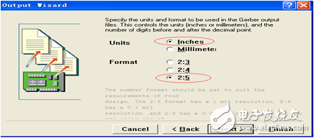
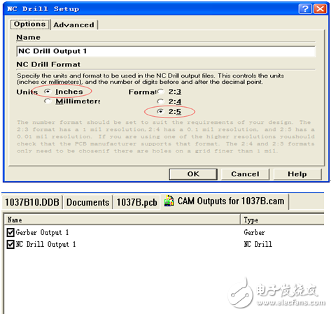
5, to this step, set the unit and format generally in accordance with the ordinary "Inches inch", "2:5 format" to export data (Figure 7 below), set up and then click Next to proceed to the next step:
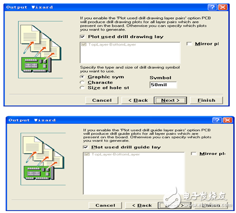
6. Immediately following the layer selection, the “Mirror†column does not need to be ticked (Figure 8). Checking the layers will cause them to be misaligned; then select the menu only to use the layer “Menu→Plot Layers→Used On. "(Figure 9), click Next when selected:
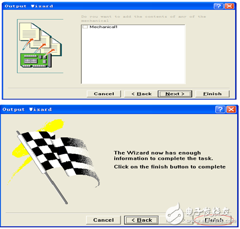
7. In the last five steps, you can directly click Next, and finally press Finish to finish the basic output of the circuit layer:
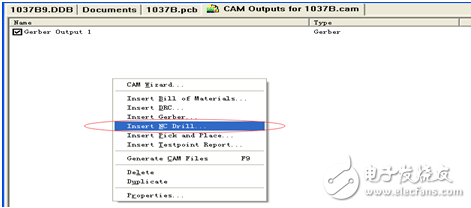
1, after the above is completed, right-click on the page that appears, the menu bar appears, select "Insert Nc Drill" output drill belt;
2. The format of the drill belt is the same as the format of the line output, and it is set according to the “Inches English†or “2:5 formatâ€, and then click OK to finish;
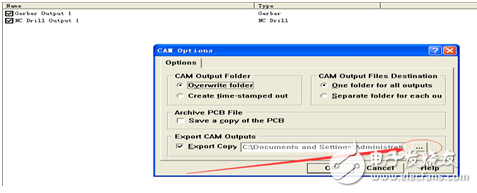
Here's where GERBER has changed. Click Tools→Preferences (shortcut T+P) to select the path to the exported file. Click OK! Finally, press F9 file to export the gerber file.
Tip one:
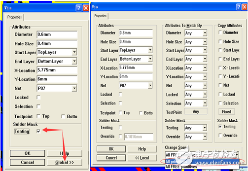
In the conversion of the two panels, the general through hole is not open the window, of course, in the CAM software can handle such problems, if we handle the conversion of the original PCB file will be very convenient! Before opening the file without switching to GERBER, use the mouse to double-click on the hole to check the setting "TenTIngd's removal → Global → Select All primiTIves → OK" (as shown below). In the GERBER, there is no green window It!
Tip two:
Sometimes the following error message will appear when you turn GERBER, and you will not be able to transfer GERBER properly.
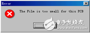
Solution: Double click here
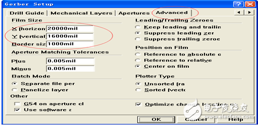
After the dialog box appears, select "Advanced". After the three values ​​in the red circle increase by 1-2 zeros, click OK. Then press F9 again to export the gerber.
Marine Diesel Generator,Marine Generator Set,Diesel Marine Generator,Boat Genset
Jiangsu Vantek Power Machinery Co., Ltd , https://www.vantekpower.com