With the development of power electronics technology, people are increasingly demanding inverter power supplies. In the case of high-power inverter power supply, the current flowing through the main circuit is very large, and the current flowing through the IGBT as a switching transistor can reach several hundred amps. Therefore, the generally selected switch has a relatively large capacity, which leads to modulation. The switching frequency should not be too high. This article first introduced the main circuit and three-loop control, followed by the introduction of unipolar frequency doubled SPWM modulation, and finally elaborated the system experimental analysis of wNN.
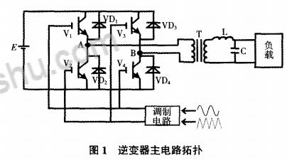
First, the main circuit and three-ring controlThe main circuit structure of the inverter is shown in Fig. 1. The main circuit adopts a full-bridge structure, and the output end is connected with an LC filter to filter out higher harmonics. Switch drive signal from the triangular wave and sine wave comparison match.
The three-loop control structure is shown in Figure 2. From the inside to the outside, the instantaneous value capacitor current loop, the instantaneous value voltage loop, and the voltage rms loop, respectively. Among them: the instantaneous value of the current loop's main role is to correct the output voltage waveform; the instantaneous value of the voltage loop is mainly used to correct the output voltage phase and improve the system's dynamic performance; the main role of the voltage rms loop is to stabilize the output voltage required The voltage amplitude.
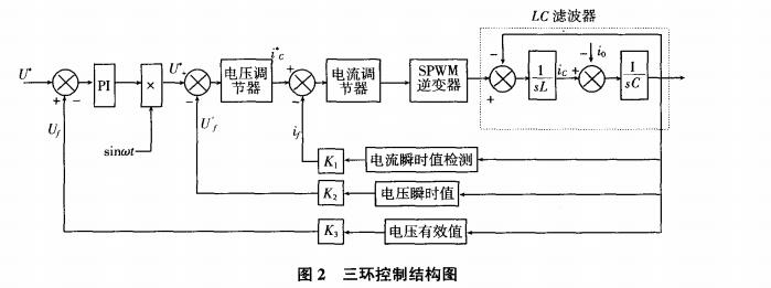
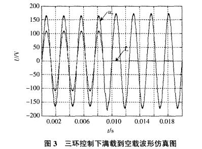
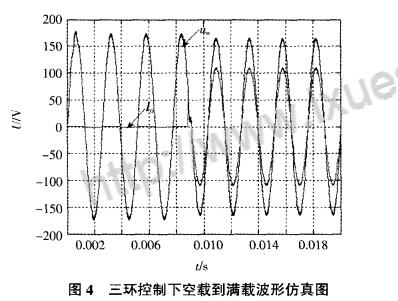
The current instantaneous value inner loop and the voltage instantaneous value outer loop adopt P regulator, and the outer loop voltage effective value loop adopts PI regulator. Fig. 3 and Fig. 4 are waveform simulation diagrams of a three-loop controlled inverter system from full-load to no-load and no-load to full-load, respectively. In Fig. 3, Uo is the output current. From Figure 3-4, it can be seen that the voltage amplitude remains basically unchanged when the load is cut, indicating that the system has better dynamic characteristics.
In the conventional SPMW wave modulation, the switching frequency and output pulse frequency are equal, but under high power conditions, the switching frequency cannot be too high, mainly due to:
1 If the switching frequency is too high, the switching loss will increase.
2 will make the switch tube fever serious, long-term operation will damage the switching device;
3 If the switching frequency is too high, there is an increased chance of a hold-up effect.
4 High-capacity switching devices that turn on and off at high speeds can generate very high voltage spikes that may cause breakdown of the switch or other components. However, lowering the switching frequency will increase the THD content in the output waveform and will not meet the final specification requirements.
In order to improve the quality of the output waveform, it is common practice to increase the LC filter parameters at the back end of the main circuit, or to increase the proportional coefficient of the regulator in the three-loop control, but increasing the LC filter parameters will increase the size of the inverter and increase the cost. , and when actually forming a digital control system. The regulator coefficient can not be too large, otherwise it will cause oscillation; therefore, the unipolar frequency doubled SPWM modulation method is applied.
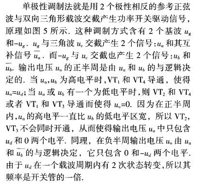
Second, unipolar frequency doubled SPWM modulation2.1, unipolar frequency doubled SPWM modulation principle
2.2. Design of filters with unipolar frequency doubled SPWM modulation
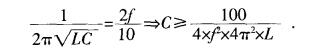
The role of the capacitor in the circuit is to form a low-pass filter with the inductor. Therefore, after the inductance value is determined, the value of the capacitor C can be determined according to the cut-off frequency of the LC filter. Since in the unipolar frequency-doubled SPWM modulation mode, the output harmonics are even-fold higher harmonics with a switching frequency of 2 times or more, the cutoff frequency of the LC filter can be taken as 1/10 of the lowest-order output harmonic. which is
In the actual circuit, due to the non-ideal characteristics of each device, the reference sine is also a non-standard sinusoidal signal, plus the effect of the dead zone on the output waveform, so the output waveform will contain low-order harmonics. By appropriately increasing the capacitance, low-order harmonics can be effectively suppressed. Put the calculated inductance value into the equation to obtain the capacitance value:
In the actual circuit design, the desirable inductance is 0.4 mH and the capacitance is 20 PF.
Under the three-loop control, using the SPWM wave unipolar frequency modulation method, the proportional control parameters in the digital control system do not need to be large, it can ensure a better output voltage waveform quality, and the output voltage signal phase, amplitude The value can meet the index requirements.
Third, the system experimental analysis wNN3.1, simulation results and analysis
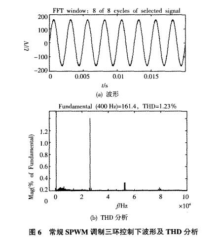
Based on the above principles, this paper uses Matlab/Simulink to build a simulation model and conduct simulation experiments. Using conventional SPWM modulation, the output waveform and waveform THD analysis results under three-loop control are shown in Figure 6. Among them: The switching frequency is 26.4 kHz; The output power is 10 kW. It can be known from Simulink's own FFT analysis that the THD content under this control is 1.23%. Among them, the third harmonic content is large and the higher harmonics have been LC. Filter out.
Using unipolar frequency-doubled SPWM modulation, the output waveform and waveform THD analysis results are shown in Figure 7 under three-loop control. Among them: The switching frequency is 10 kHz and the output power is 10 kW. The Simulink's own FFT analysis shows that the THD content under this control is 0.75%. Among them, the even harmonics content is large and the higher harmonics have been filtered by LC. Filter out.
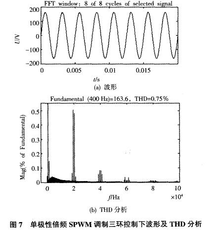
From the comparison of the above results, when the unipolar frequency-doubled SPWM modulation method is used, the switching frequency is only 10 kHz, but the THD value of the output voltage is less than 1%; while the conventional SPWM modulation method, the switching frequency is 26.4 kHz, and the THD value is also Only 1.23%. After the switching frequency of 10 kHz, the output voltage pulse frequency is 20kHz. The THD value is similar to the switching frequency of 26.4kHz, indicating that the unipolar frequency-doubled modulation method is effective.
3.2, experimental results and analysis
The experimental verification is based on the above simulation experiments. First obtain the unipolar frequency doubled SPW M drive signal, as shown in Figure 8. When the system switches the load, the output voltage and output current waveform are shown in Figure 9. As can be seen from Figure 9, the system can recover the voltage amplitude after several cycles of adjustment during the load switching, indicating that the system has better dynamic performance under the three-loop control and is consistent with the simulation results. Waveforms and harmonic distortion rates under conventional bipolar SPWM modulation are shown in Figure 10. As can be seen from Figure 10, THD is 2.52%. In unipolar frequency doubler
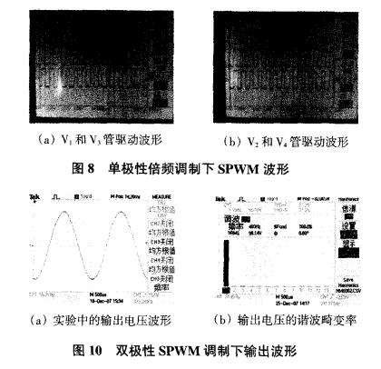
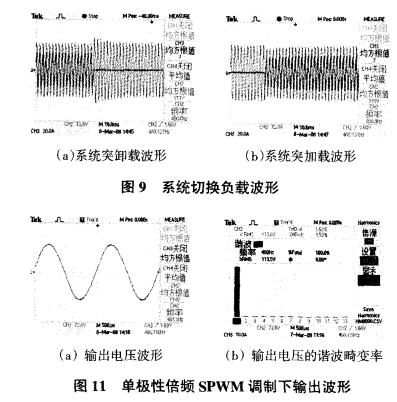
The output voltage waveform and harmonic distortion ratio under SPW M modulation are shown in FIG. 11 . As can be seen from Figure 11, THD is only 1.53%.
IV. ConclusionIn order to solve the problem that the switching frequency of the switch cannot be too high under high power conditions, the unipolar frequency-doubled SPWM wave modulation method is combined with the loop control for simulation research and experimental verification. The results show that this method is effective in high-power inverter power supplies and can achieve higher THD output waveforms.
201-400Kva Diesel Generator,Super Silent Power Generator,400Kva Diesel Generator,Super Silent Type Diesel Generator
Shanghai Kosta Electric Co., Ltd. , https://www.generatorksd.com