TDR is an abbreviation of multiple English words, including: Time-Domain Reflectometry—a time-domain reflectometry technique, a remote measurement technique that analyzes reflected waves, and grasps the condition of the measured object at a remote location. TDR is mainly composed of three parts: fast edge signal generator, sampling oscilloscope and probe system.
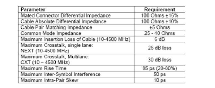
TDR test principle and test methodWith the increasing speed of digital circuits, the transmission rate of signals on PCBs has become higher and higher. For example, the signal rate of PCI-Express has reached 2.5Gb/s, and the signal rate of SATA has reached 3Gb/s. New standards such as PCI-Express II, XAUI, and 10G Ethernet work faster. As the data rate increases, the rise time of the signal will be faster. When the signal on the fast rising edge encounters an impedance discontinuity point on the circuit board, it will generate more reflection. The reflection of these signals will change the shape of the signal, so the line impedance is a key factor that affects the signal integrity. For high-speed circuit boards, it is very important to ensure the continuity of the impedance in the signal transmission path to avoid large reflections of the signal. Correspondingly, for the test, it is also necessary to test the impedance change on the high-speed circuit board signal transmission path and analyze the cause of the problem to better locate the problem. For example, standards such as PCI-Express and SATA need to accurately measure the impedance of the transmission line. . The following table shows the impedance and attenuation requirements of the SATA cables and connectors connected to the system:
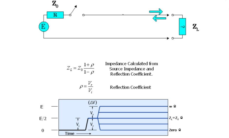
A quick and effective way to perform an impedance test is the TDR (Time Domain Reflectometry) method. The working principle of TDR is based on the transmission line theory, and the working mode is somewhat like radar. As shown in the figure below, when a step pulse is added to the line under test, reflection occurs at the impedance discontinuity point. If the source impedance Z0 is known, the impedance ZL of the measured point can be calculated according to the reflection coefficient Ï. .
The simplest TDR measurement configuration is to add a step pulse generator to the broadband oscilloscope module. The step pulse generator emits a step pulse with a fast rising edge while the receiving module captures the time domain waveform of the reflected signal. If the impedance of the device under test is continuous, the signal is not reflected. If there is a change in impedance, the signal will be reflected back. The distance of the impedance discontinuity point from the receiving end can be judged according to the time of the reflected echo, and the impedance change of the corresponding point can be judged according to the reflected back amplitude. The following figure shows how the TDR works and the TDR waveform for a DUT.
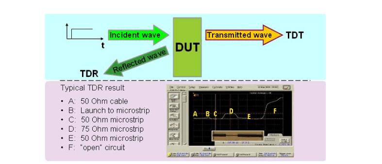
TDR usually shows reflection and impedance change, TDT (time domain transmission) usually shows transmission delay. Discontinuities in the impedance of the device or channel can cause distortion in the transmitted signal, so TDR/TDT is an important tool for enhancing signal integrity.
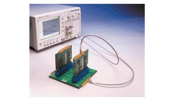
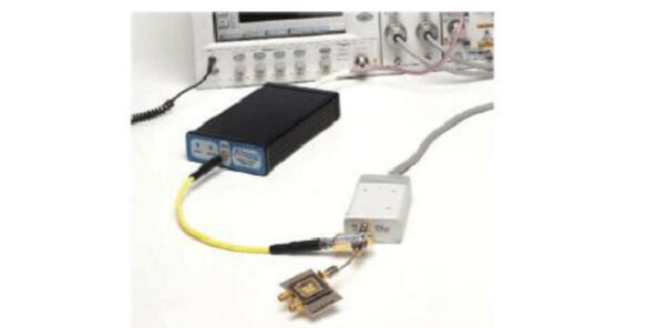
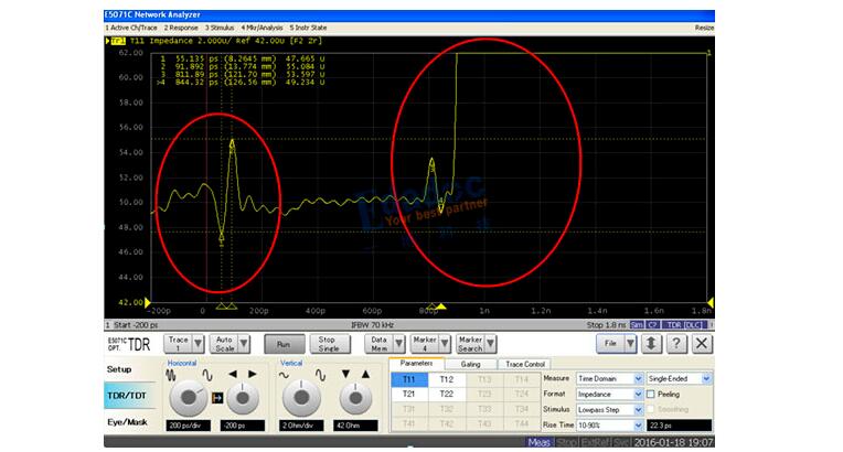
For years, the powerful combination of the Agilent 86100 Series Infiniium DCA host and the 54754A differential TDR module has provided an excellent solution for TDR/TDT measurements. In order to meet the stringent requirements of current high-speed digital serial interfaces, TDR/TDT measurement functions have also undergone major improvements, making it easy to obtain accurate results. The following figure shows an example of a TDR test using the Agilent 86100 and 54754A modules.
A) TDR calibration is the fastest way to get correct results
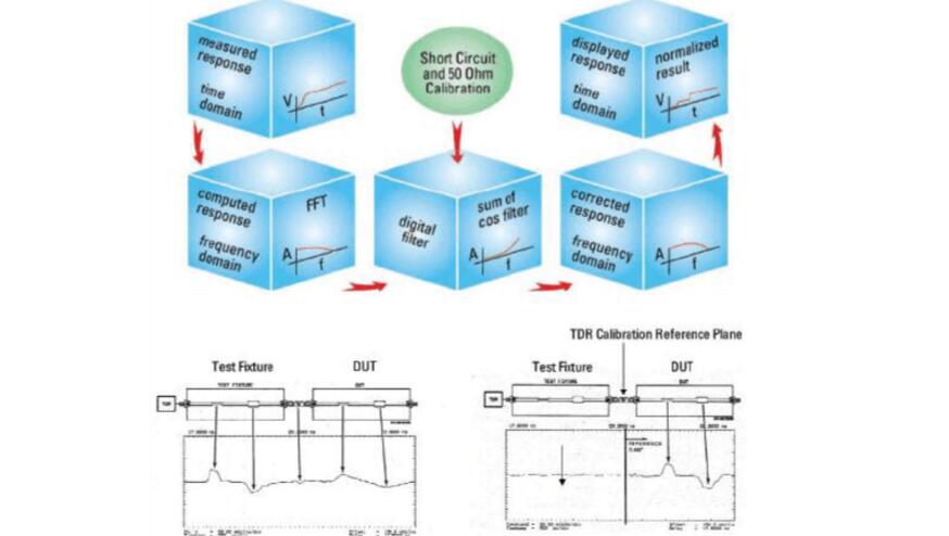
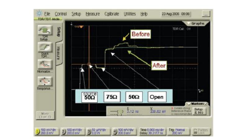
To obtain the correct test results, systematic errors due to test fixtures or cables must be properly eliminated. Agilent TDR calibration uses digital filter technology, which uses a short-circuit and load reference device to establish a calibration plane that eliminates systematic errors to provide accurate results. The following figure shows the working principle of TDR calibration and the comparison of the test results before and after TDR calibration. It can be seen that the calibrated reflection waveform more clearly reflects the change of impedance.
B) S-parameter measurement
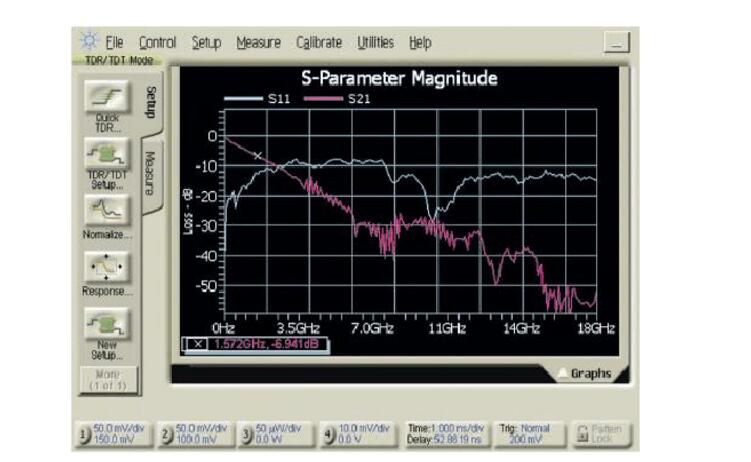
86100C Option 202 The S-parameter (S11 Return Loss or S21 Insertion Loss) in the frequency domain can be quickly obtained from the results of TDR/TDT in the time domain with just a touch of a button.
C) Correction of multiple reflections:
When there are multiple impedance discontinuities in the system under test, reflections will occur at each point, and the reflected waveform may be reflected back when it encounters an impedance discontinuity point, which will cause TDR waveform distortion. Not conducive to accurate measurement. The 86100C option 202 adds multiple reflection correction to compensate for multiple reflections on TDR waveforms. The following is the comparison of TDR waveforms before and after multiple reflection correction. It can be seen that the corrected waveform removes the effects of multiple reflections.
D) Quality of TDR step pulse
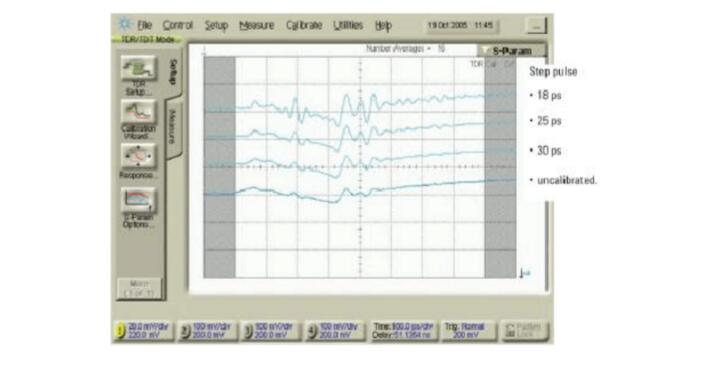
The quality of the TDR step pulse sent to the device under test affects the result of the TDR measurement. The well-designed 54754A module minimizes deviations to obtain clear pulses with small national weights and oscillations, reducing measurement errors. The digital filtering obtained from the TDR calibration can simulate step pulses of different rise times to verify the reflection of the actual signal pulse. Using TDR calibration can also simulate the reflection of faster step pulses. The following figure shows the reflection results of step pulses with different rise times.
E) Improve resolution by accelerating the actual step pulse
The Picosecond Pulse Lab's source enhancement module provides finer range resolution by applying a 9pS rise time step pulse. When using the source enhancement module to work with higher bandwidth receiver modules, Agilent's 86118A is the best receiver module with 70G bandwidth and far-end probe to eliminate performance degradation due to connecting cables. The following figure shows an example of a TDR test using a pulse enhancement module and a wideband receiver.
F) Comprehensive differential testing through PLTS
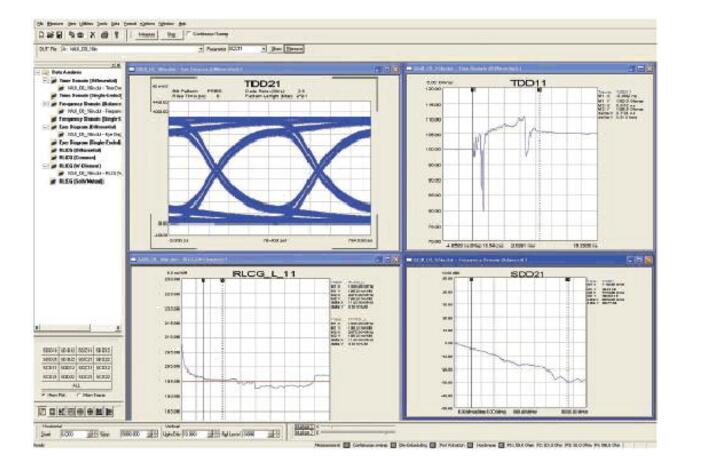
The TDR-based N1930A physical layer test solution provides a complete solution for detailed differential line testing. The system has 16-phase S-parameters and a wide range of calibration tests. Agilent's PLTS system also has an eye diagram simulation function that simulates the shape of the eye after the actual signal is transmitted over the wire and extracts the RLCG model of the wire for simulation modeling analysis. The following figure is an example of the analysis result of PLTS:
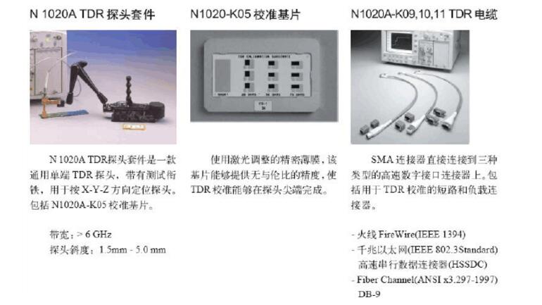
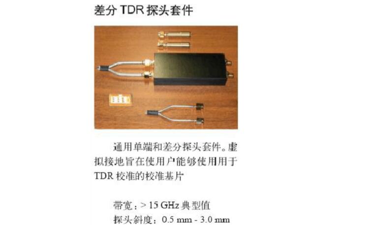
G) TDR attachments:
In order to facilitate TDR testing while minimizing test errors, Agilent also offers many TDR test accessories.
Impedance is not an imaginary stable straight line, but it is ups and downs. The front-end and back-end will be affected by the probe or open circuit, and in the middle due to the production process, there will be fluctuations.
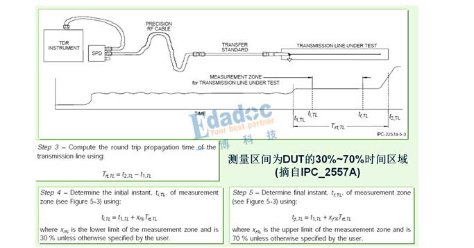
So how do we judge the test result? How to determine whether the PCB impedance produced meets the requirements? First take a look at the IPC specification. The measurement interval recommended by IPC2557A is between 30% and 70% of the DUT.
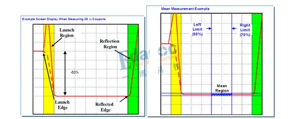
Let's take a look at the test habits of Intel and nowadays mainstream PCB manufacturers. To avoid the influence of the Launch area and the reflection area, the test interval is recommended to be 50% to 70% of the DUT area.
To test the line impedance with TDR, we must first understand the test interval requirements in order to accurately understand the measurement results.
2. Effect of probe on impedance test resultsIn general, the following probes are used for TDR testing:
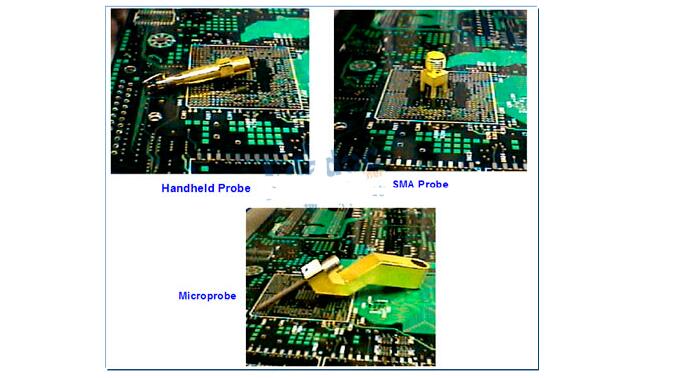
Among them, the plate factory usually uses the handheld probe to measure, Probe's influence is inductive. SI laboratories often use SMAs to connect test cables. SMAs may appear capacitive in impedance tests. The effect of the two probes on the test results is shown in the figure below:
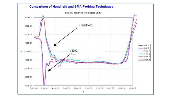
Due to Probe's perceptual or capacitive influences, the final DUT test results will have a slight deviation.
VFD Part Grid,Grid for VFD Part,Electronics Controlling Grid VFD
SHAOXING HUALI ELECTRONICS CO., LTD. , https://www.cnsxhuali.com