The sensing element is used to convert the associated physical quantity into an electrical signal. For example, a Wheatstone bridge can be used to convert pressure into electrical output. Many sensing elements are inherently non-linear. In other words, their output is not linearly proportional to the physical quantity they are measuring. The output changes nonlinearly due to changes in the associated physical quantities.
A sensor signal conditioner is used to correct the nonlinear characteristics of the output of the sensing element. In this article, we have studied two widely used methods for correcting the nonlinearity of a sensing element: 1) look-up table (LUT) or interpolation; 2) polynomial or curve fitting. The paper compares the two methods and discusses the trade-off between the two methods.
Sensing element and sensor signal conditionerThe sensor or transmitter includes a sensing element and a signal conditioner. Sensing elements such as Wheatstone bridges or hot wire anemometers are used to convert physical pressures, such as pressure or air mass flow, into electrical signals, respectively. The sensor signal conditioner is used to process the non-ideal characteristics of the sensing element output and send the signal to the controller. Figure 1 shows the overall block diagram of the ecosystem.
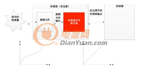
Figure 1: Block diagram of the sensor showing the associated physical quantity (x), sensing element output (y), and conditioned sensor output (z).
Figure 1 shows that the measured physical quantity is x, the output of the sensing element is y, and the processed sensor signal regulator output is z. The sensor signal conditioner is used to handle non-ideal characteristics such as nonlinearity, temperature change, and dynamic response of the sensing element output. This article discusses how to handle the nonlinearity of the sensing element output.
Sensing element nonlinearityAlthough the nonlinearities of the sensing elements have different forms, we will discuss a specific nonlinear form, second-order nonlinearity, in this paper so that we can understand how to linearize the output using a sensor signal conditioner. Note that these concepts can be generalized to arbitrary nonlinearities.
If the input and output of a sensing element have a mathematical relationship as shown in Equation 1, the sensing element can be considered to have a second-order nonlinearity:
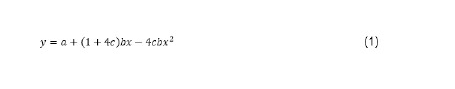
In the formula:
a = sensing component offset, which is defined as the output of the sensing component when the measured physical quantity is at its minimum
b = sensing component span, defined as the difference between the sensing element outputs when determining the maximum and minimum physical quantities
c = second-order nonlinearity of the sensing element
x = measured physical quantity
y = the output of the sensing element, a function of x
For example, consider a nonlinear sensing element with the following example parameters:
• x is a value between 0 and 1. That is, the physical quantity has been normalized, so there is no unit
• a= 0
• b = 1
• c = 10% full scale (FS), where FS = b; in other words, the sensing element has a 10% nonlinearity.
In this case, the functional relationship between the output of the sensing element and the input is as shown in Equation 2.
Figure 2 shows a graph of Equation 2 for a normalized input x varying from 0 to 1. It can be inferred from the graph of Fig. 2 that the output of the sensing element is 0.6 when x = 0.5. If the output of the sensing element is completely linear, the output will be 0.5. That is, the sensing element has a 10% FS deviation at the midpoint. This is the bulge that appears on the output of the sensing element with second-order nonlinearity.
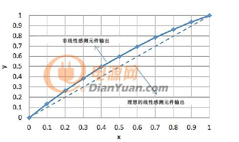
Figure 2: Output of a nonlinear sensing element. Please pay attention to the bulging of the output line.
Solar Generator,Wind Power Generator,Home Generators,Solar Generator
Shaoxing AnFu Energy Equipment Co.Ltd , https://www.sxanfu.com