Q: Why is my processor power consumption greater than the value given in the data sheet?
A: A device that consumes too little power -- yes, it does have this -- it causes trouble. But this is very rare. The more common situation I deal with is that customers complain that the device consumes more power than the data model claims.

I remember once, the customer walked into my office with the processor board, saying that it was too power-consuming and drained the battery. Since we have proudly claimed that this processor is an ultra-low power device, the burden of proof is on our side. I am going to follow the usual practice of cutting off the power of different devices on the board one by one until I find the real messenger. Then I think of a similar case not long ago. The "culprit" of that case is a single hanging on the power rail and the ground. There is no current limiting resistor between the LEDs. The LED is ultimately ineffective because it is overcurrent, or simply because it is boring, I can't be completely sure, but this is a digression, let's not talk about it for the time being. From experience, the first thing I did was to check for sparkling LEDs on the board. But unfortunately, this time there is no similar hope for the dawn of the problem. In addition, I found that the processor is the only device on the board, and no other device can blame me. A message from the customer next made me feel even lower: through laboratory tests, he found that power consumption and battery life were at the expected level, but after the system was deployed to the site, the battery was running out quickly. Such problems are the most difficult to solve because they are very difficult to reproduce the "first case." This adds analog unpredictability and challenges to the problems of the digital world, which is usually only a predictable, simple world of 1 and 0.
In the simplest sense, there are two main aspects of processor power consumption: the core and I/O. When it comes to suppressing kernel power consumption, I check things like: PLL configuration/clock speed, kernel supply rails, and core computation. There are several ways to reduce the power consumption of the core, such as lowering the core clock speed, or executing some instructions to force the core to stop running or go to sleep/hibernate. If I suspect that I/O has swallowed up all power consumption, I will focus on the I/O power supply, the I/O switching frequency, and the load it drives.
I can only explore these two aspects. As a result, the problem has nothing to do with the kernel, so it must be related to I/O. At this point, the customer stated that he used the processor purely for calculations and had very little I/O activity. In fact, most of the available I/O interfaces on the device are not used.
"Wait! Some I/Os are not used. You mean these I/O pins are not used. How did you connect them?"
"Of course, I didn't connect them anywhere!"
"It turns out!"
This is an ecstatic moment, I finally found the problem. Although I didn't scream along the way, it took me a while to press the excitement and then sit down and explain to him.
A typical CMOS digital input looks like this:

Figure 1. Typical CMOS input circuit (left) and CMOS level logic (right)
When the input is driven at the recommended high (1) or low (0) level, the PMOS and NMOS FETs are turned on one at a time and never turn on at the same time. The input drive voltage has an uncertainty region called the "threshold region" where the PMOS and NMOS may be partially turned on at the same time, creating a leakage path between the supply rail and ground. This can happen when the input is floating and encounters spurious noise. This explains both the fact that the power consumption on the customer's board is high and why the high power consumption happens randomly.
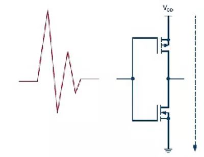
Figure 2. Both PMOS and NMOS are partially turned on, creating a leakage path between the power supply and ground.
In some cases, this can cause conditions such as latch-up, where the device continues to draw excessive current and eventually burns out. It can be said that this problem is easier to find and solve, because the device in front of it is smoking, the evidence is conclusive. The problems reported by my clients are even more difficult to deal with, because when you test in the cool environment of the lab, it's fine, but when you get to the site, it can cause a lot of trouble.
Now that we know the root cause of the problem, the obvious solution is to drive all unused inputs to an active logic level (high or low). However, there are some minor issues to be aware of. Let's look at a few cases where CMOS input is not handled properly. We need to expand the scope, considering not only the complete disconnect/floating input, but also the input that seems to be connected to the appropriate logic level.
If you only connect the pin to the supply rail or ground through a resistor, you should pay attention to the size of the pull-up or pull-down resistor used. Together with the pull/sink current of the pin, it may shift the actual voltage of the pin to an undesired level. In other words, you need to make sure that the pull-up or pull-down resistors are strong enough.
If you choose to drive the pin in an active mode, make sure that the drive strength is good enough for the CMOS load used. If this is not the case, the noise around the circuit may be strong enough to exceed the drive signal, forcing the pin to enter an unexpected state.
Let's study several situations:
Processors that work properly in the lab may be inexplicably restarted in the field because noise is coupled into the RESET line that does not have a strong pull-up resistor.
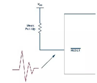
Figure 3. Noise coupling into the RESET pin with weak pull-up resistor may cause the processor to restart
2. Imagine a CMOS input belonging to a gate driver that controls a high-power MOSFET/IGBT that turns on unexpectedly when it should be turned off! It's awful.
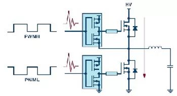
Figure 4. Noise overdrive A weakly driven CMOS input gate driver that causes a high voltage bus short
Another related but less obvious problem situation is when the rise/fall of the drive signal is very slow. In this case, the input may stay at the intermediate level for a certain period of time, causing various problems.
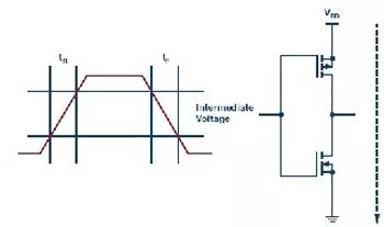
Figure 5. The rise/fall of the CMOS input is very slow, causing a temporary short during the transition.
We have discussed some of the problems that can occur with CMOS inputs in a general sense. It is worth noting that, in terms of design, some devices are better at handling these problems than others. For example, devices with Schmitt Trigger inputs can better handle signals with high noise or slow edges.
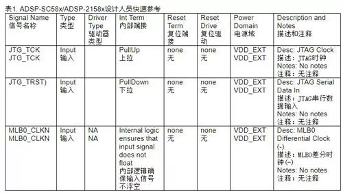
Some of our latest processors have also noticed this problem and have taken special precautions in the design or issued clear guidelines to ensure smooth operation. For example, the ADSP-SC58x/ADSP-2158x data sheet clearly states that some pins have internal termination resistors or other logic to ensure that these pins do not float.
Finally, as you often say, it's important to do all the finishing work correctly, especially with CMOS digital inputs.
4G Module,4G Router Module,4G Wifi Module,4G Lte Wifi Module
Shenzhen MovingComm Technology Co., Ltd. , https://www.movingcommiot.com